


![[The AI Show Episode 145]: OpenAI Releases o3 and o4-mini, AI Is Causing “Quiet Layoffs,” Executive Order on Youth AI Education & GPT-4o’s Controversial Update](https://www.marketingaiinstitute.com/hubfs/ep%20145%20cover.png)


_NicoElNino_Alamy.jpg?width=1280&auto=webp&quality=80&disable=upscale#)


![Standalone Meta AI App Released for iPhone [Download]](https://www.iclarified.com/images/news/97157/97157/97157-640.jpg)


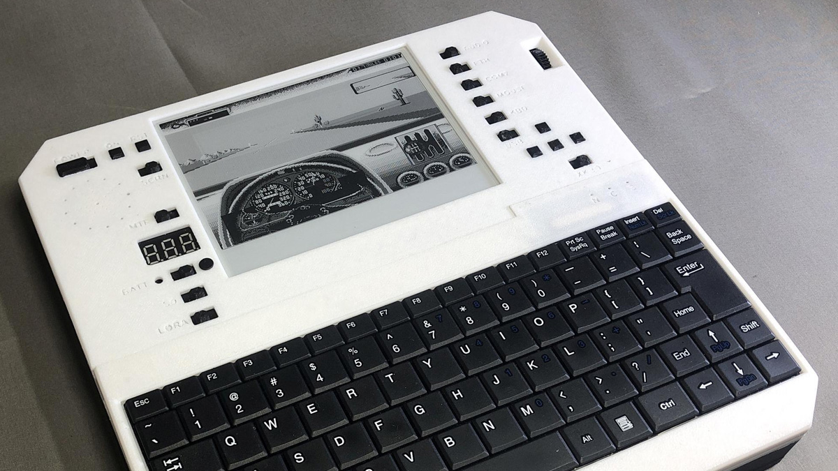
The DIY 1982 Picture Phone
If you’ve only been around for the Internet age, you may not realize that Hackaday is the successor of electronics magazines. In their heyday, magazines like Popular Electronics, Radio Electronics, …read more

If you’ve only been around for the Internet age, you may not realize that Hackaday is the successor of electronics magazines. In their heyday, magazines like Popular Electronics, Radio Electronics, and Elementary Electronics brought us projects to build. Hacks, if you will. Just like Hackaday, not all readers are at the same skill level. So you’d see some hat with a blinking light on it, followed by some super-advanced project like a TV typewriter or a computer. Or a picture phone.
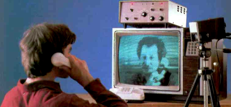
In 1982, Radio Electronics, a major magazine of the day, showed plans for building a picture phone. All you needed was a closed-circuit TV camera, a TV, a telephone, and about two shoeboxes crammed full of parts.
Like many picture phones of its day, it was stretching the definition a little. It actually used ham radio-style slow scan TV (SSTV) to send a frame of video about once every eight seconds. That’s not backwards. The frame rate was 0.125 Hz. And while the resulting 128 x 256 image would seem crude today, this was amazing high tech for 1982.
Slow Scan for the Win
Hams had been playing with SSTV for a long time. Early experiments used high-persistence CRTs, so you’d see the image for as long as the phosphor kept glowing. You also had to sit still for the entire eight seconds to send the picture.
It didn’t take long for hams to take advantage of modern circuits to capture the slow input and convert it to a normal TV signal for as long as you wanted, and that’s what this box does as well. Early “scan converters” used video storage tubes that were rejects (because a perfect new one might have cost $50,000). However, cheap digital memory quickly replaced these storage tubes, making SSTV more practical and affordable.

Still, it never really caught on for telephone networks. A few years later, a few commercial products offered similar tech. Atari made a phone that was bought up by Mitsubishi and sold as the Luna, for example, around 1986. Mitsubishi, Sony, and others tried, unsuccessfully, to get the market to accept these slow picture phones. Between the cost of making a call and a minimum of $400 to buy one, though, it was a hard sell.
You might think this sounds like a weekend project with a Pi-Cam, and you are probably right if you did it now. But in 1982, the amount of work it took to make this work was significant. It helped that it used MM5280 dynamic RAM chips, which held a whopping 4,096 bits (not bytes) of memory. The project needed 16 of the chips, which, at the time, were about $5 each. Remember that $80 in those days was a lot more than $80 today, and you had to buy the rest of the parts, the camera (the article estimates that’s $150, alone), and so on. This wasn’t a poor high school student project.
Robot Kits
You could buy entire kits or just key parts, which was a common thing for magazines to do in those days. The kits came from Robot Research, which was known for making SSTV equipment for hams, so it makes sense that they knew how to do this. The author mentions that “this project is not for beginners.” He explains there are nearly 100 ICs on a “tightly-packed double-sided PC board.”
The device had two primary inputs: fast scan from the camera and slow scan from the phone line. Both could be digitized and stored in the memory array. The memory can also output fast scan TV for the monitor or slow scan for the phone line. Obviously, the system was half duplex. If you were sending a picture, you wouldn’t expect to receive a picture at the same time.

The input conversion is done with comparators for speed. Luckily, the conversion is only four bits of monochrome, so you only need 16 (IC73-80) to get the job done. The memory speed was also a concern. Each memory chip’s enable line activated while the previous chip’s was half way through with a cycle.
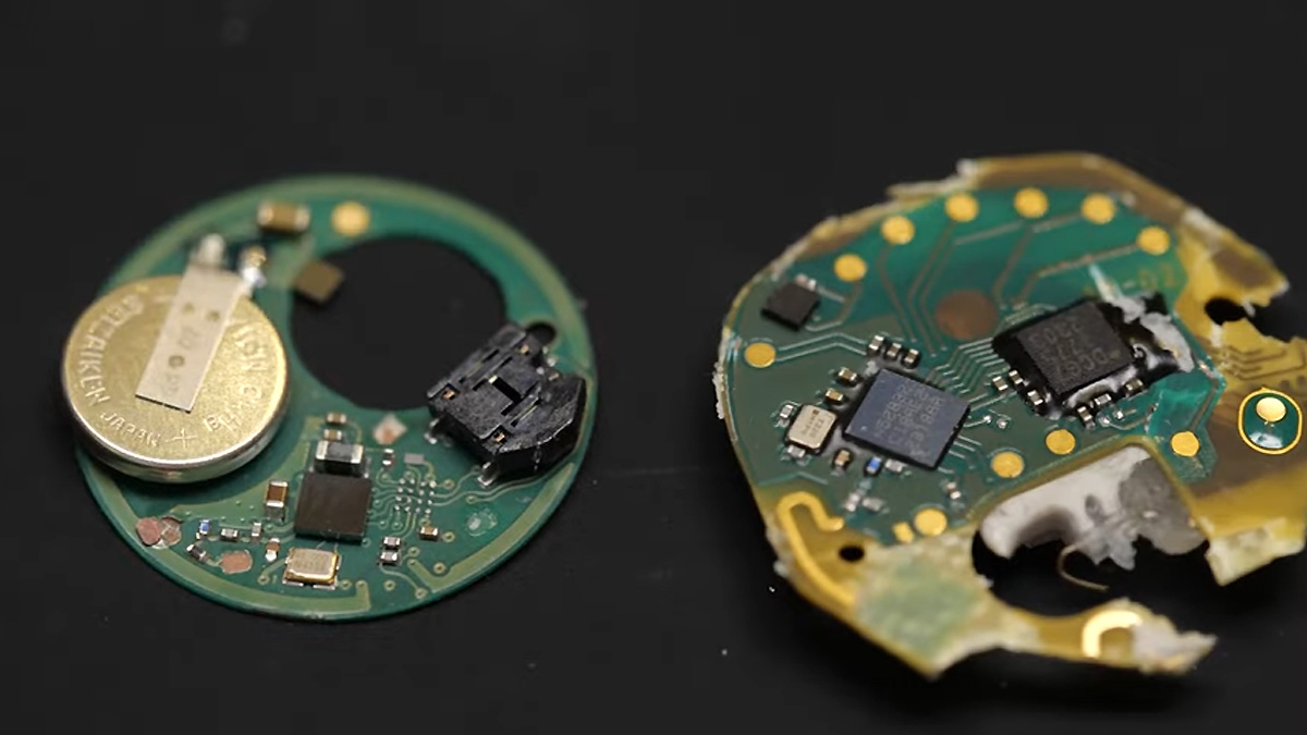
Since there is no microcontroller, the design includes plenty of gates, op amps, bipolar transistors, and the like. The adjacent picture shows just the device’s main board!
Lots of Parts
If you want to dig into the details, you’ll also want to look at part 2. There’s more theory of operation there and the parts list. The article notes that you could record the tones to a cassette tape for later playback, but that you’d “probably need a device from your local phone company to couple the Picture Phone to their lines.” Ah, the days of the DAA.
They even noted in part 2 that connecting a home-built Picture Phone directly to the phone lines was illegal, which was true at the time. Part 3 talks even more about the phone interface (and, that same issue has a very cool roundup of all the computers you could buy in 1982, ranging from $100 to $6,000). Part 4 was all about alignment and yet more about the phone interface.
Alignment shouldn’t have been too hard. The highest tone on the phone line was 2,300 Hz. While there are many SSTV standards today for color images, this old-fashioned scheme was simple: 2,300 Hz for white and 1,500 Hz for black. A 1,200 Hz tone provided sync signals. Interestingly, sharp jumps in color could create artifacts, so the converters use a gray code to minimize unnecessary sharp jumps in value.
The Phone Book
It wouldn’t make sense to make only one of these, so we wonder how many pairs were built. The magazine did ask people to report if they had one and intended to publish a picture phone directory. We don’t know if that ever happened, but given what a long-distance phone call cost in 1982, we imagine that idea didn’t catch on.
The video phone was long a dream, and we still don’t have exactly what people imagined. We would really like to replicate this picture phone on a PC using GNU Radio, for example.