


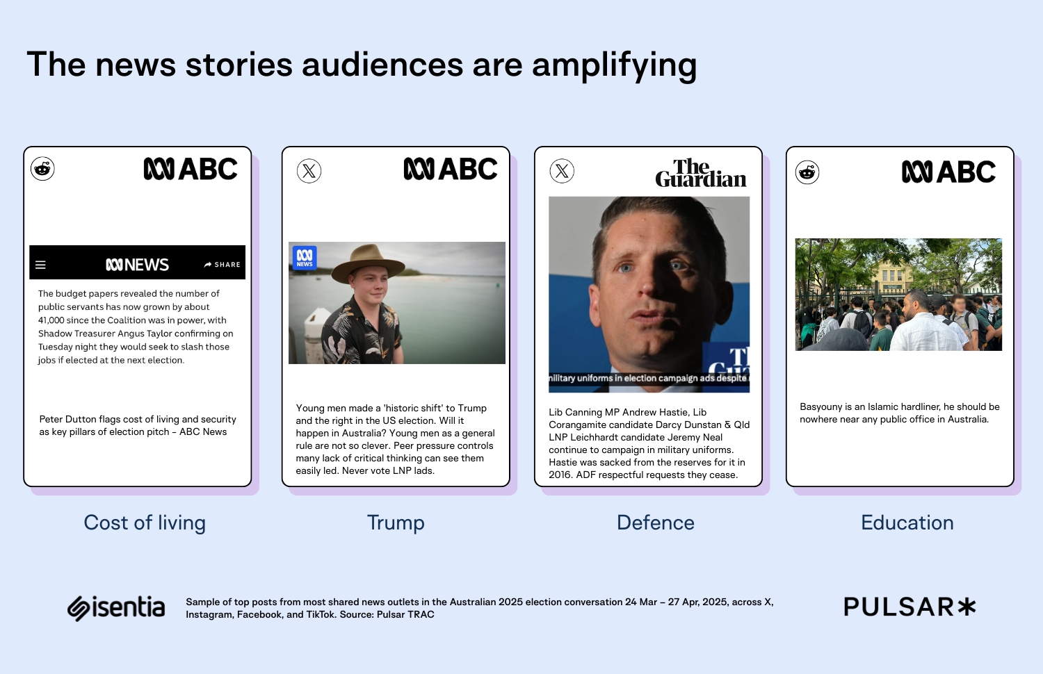
![[The AI Show Episode 146]: Rise of “AI-First” Companies, AI Job Disruption, GPT-4o Update Gets Rolled Back, How Big Consulting Firms Use AI, and Meta AI App](https://www.marketingaiinstitute.com/hubfs/ep%20146%20cover.png)


.jpg?width=1920&height=1920&fit=bounds&quality=70&format=jpg&auto=webp#)


.jpg?#)


_Alexey_Kotelnikov_Alamy.jpg?width=1280&auto=webp&quality=80&disable=upscale#)
_Brian_Jackson_Alamy.jpg?width=1280&auto=webp&quality=80&disable=upscale#)

_Steven_Jones_Alamy.jpg?width=1280&auto=webp&quality=80&disable=upscale#)


 Stolen 884,000 Credit Card Details on 13 Million Clicks from Users Worldwide.webp?#)


![Roku clarifies how ‘Pause Ads’ work amid issues with some HDR content [U]](https://i0.wp.com/9to5google.com/wp-content/uploads/sites/4/2025/05/roku-pause-ad-1.jpg?resize=1200%2C628&quality=82&strip=all&ssl=1)
![Look at this Chrome Dino figure and its adorable tiny boombox [Gallery]](https://i0.wp.com/9to5google.com/wp-content/uploads/sites/4/2025/05/chrome-dino-youtube-boombox-1.jpg?resize=1200%2C628&quality=82&strip=all&ssl=1)


![Apple Seeds visionOS 2.5 RC to Developers [Download]](https://www.iclarified.com/images/news/97240/97240/97240-640.jpg)
![Apple Seeds tvOS 18.5 RC to Developers [Download]](https://www.iclarified.com/images/news/97243/97243/97243-640.jpg)

![Apple Releases macOS Sequoia 15.5 RC to Developers [Download]](https://www.iclarified.com/images/news/97245/97245/97245-640.jpg)


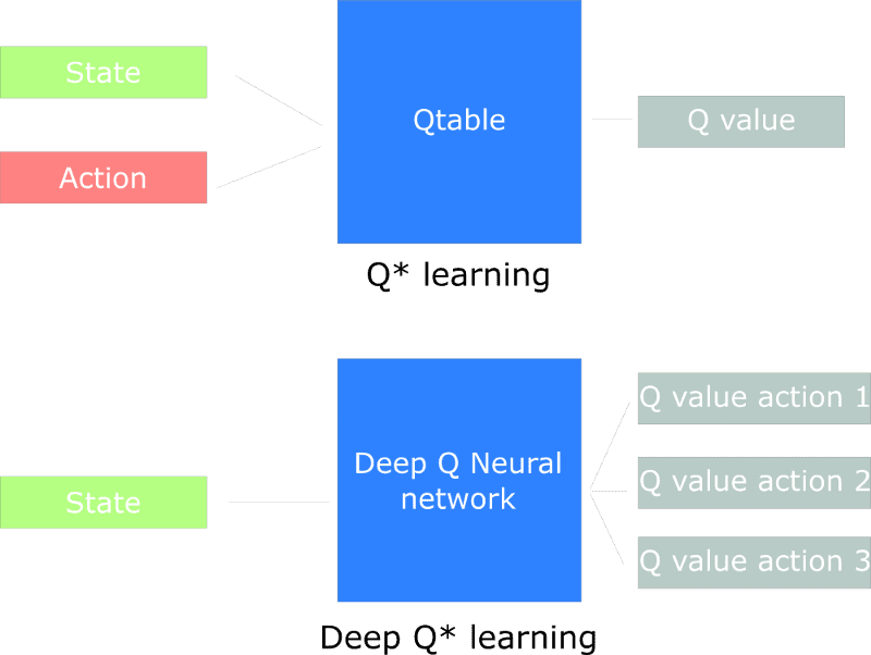
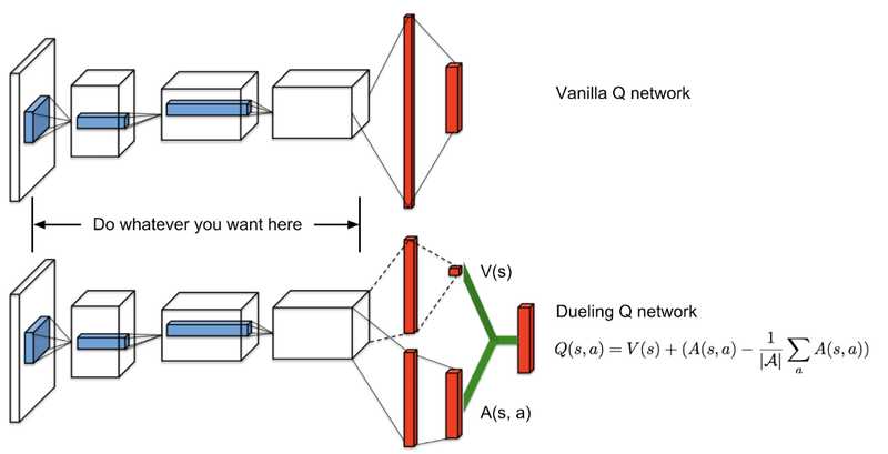
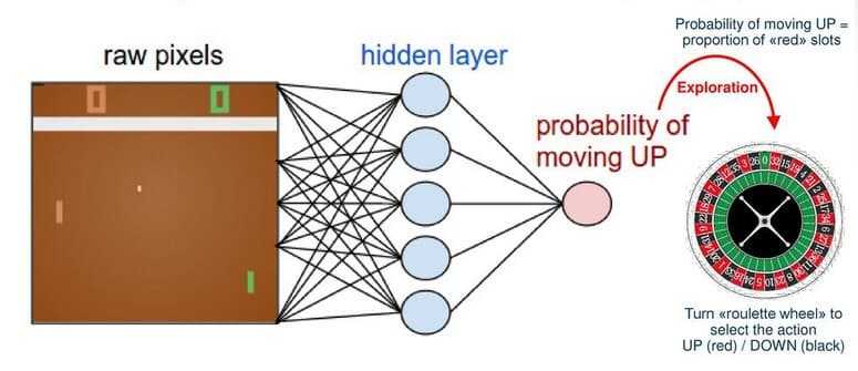
How do you develop code for an FPGA?
Developing code for an FPGA (like your DE1-SoC) involves several key steps that differ from traditional software development. Here's a comprehensive guide: 1. Design Phase a) Hardware Architecture Design Define your system's block diagram Identify components needed: Data paths Control logic Memory interfaces I/O peripherals Consider clock domains and timing requirements b) Choose Your HDL Verilog: C-like syntax, popular in industry VHDL: Strongly typed, common in defense/aerospace SystemVerilog: Enhanced Verilog with verification features HLS (High-Level Synthesis): C/C++ to HDL (e.g., Intel HLS) 2. Coding Phase a) RTL Coding (Register Transfer Level) Example Verilog module: verilog module pwm_generator ( input clk, input reset, input [7:0] duty_cycle, output reg pwm_out ); reg [7:0] counter; always @(posedge clk or posedge reset) begin if (reset) begin counter

Developing code for an FPGA (like your DE1-SoC) involves several key steps that differ from traditional software development. Here's a comprehensive guide:
1. Design Phase
a) Hardware Architecture Design
Define your system's block diagram
Identify components needed:
- Data paths
- Control logic
- Memory interfaces
- I/O peripherals
Consider clock domains and timing requirements
b) Choose Your HDL
- Verilog: C-like syntax, popular in industry
- VHDL: Strongly typed, common in defense/aerospace
- SystemVerilog: Enhanced Verilog with verification features
- HLS (High-Level Synthesis): C/C++ to HDL (e.g., Intel HLS)
2. Coding Phase
a) RTL Coding (Register Transfer Level)
Example Verilog module:
verilog
module pwm_generator (
    input clk,
    input reset,
    input [7:0] duty_cycle,
    output reg pwm_out
);
    reg [7:0] counter;

    always @(posedge clk or posedge reset) begin
        if (reset) begin
            counter <= 0;
            pwm_out <= 0;
        end
        else begin
            counter <= counter + 1;
            pwm_out <= (counter < duty_cycle);
        end
    end
endmodule
b) Key Coding Practices:
- Think concurrently (not sequentially like software)
- Register all outputs for better timing
- Use proper reset strategies
- Avoid latches unless specifically needed
- Follow synchronous design principles
3. Simulation & Verification
a) Testbench Development
verilog
module tb_pwm();
    reg clk, reset;
    reg [7:0] duty;
    wire pwm;

    pwm_generator dut(.*);

    initial begin
        clk = 0;
        forever #5 clk = ~clk;
    end

    initial begin
        reset = 1; duty = 0;
        #20 reset = 0;
        #10 duty = 85;  // 33% duty
        #1000 $finish;
    end
endmodule
b) Verification Tools:
- ModelSim/QuestaSim (RTL simulation)
- Vivado/Xcelium (alternative simulators)
- Universal Verification Methodology (UVM) for complex designs
4. Synthesis & Implementation (Using Quartus for DE1-SoC)
a) Design Flow:
- Analysis & Synthesis: Convert HDL to generic gates
- Technology Mapping: Convert to FPGA primitives (LUTs, DSPs, etc.)
- Place & Route: Physical implementation
- Timing Analysis: Verify design meets timing constraints
b) Constraint Files (.sdc for Quartus):
tcl
create_clock -name clk50 -period 20 [get_ports clk]
set_input_delay -clock clk50 2 [all_inputs]
set_output_delay -clock clk50 3 [all_outputs]
5. Debugging & Validation
a) On-Chip Debugging Tools:
- SignalTap Logic Analyzer (Intel/Quartus)
- ChipScope (Xilinx)
- ILA (Integrated Logic Analyzer) in Vivado
b) Physical Debugging:
- Oscilloscope for signal integrity
- Logic Analyzer for multi-signal capture
- Protocol Analyzers (for interfaces like USB, PCIe)
6. Optimization Techniques
a) Area Optimization:
- Resource sharing
- Time-multiplexing
- Optimal state encoding
b) Speed Optimization:
- Pipeline long combinational paths
- Register balancing
- Multi-cycle paths
c) Power Optimization:
- Clock gating
- Power-aware synthesis
- Dynamic frequency scaling
DE1-SoC Specific Tips:
- Use Platform Designer (Qsys) for system integration
- Leverage HPS-FPGA bridges for ARM-FPGA communication
- Utilize onboard peripherals (VGA, Audio, ADCs)
- Consider partial reconfiguration for dynamic updates
Development Tools Comparison:
Tool Vendor Best For
Quartus Prime Intel Cyclone/Stratix FPGAs
Vivado Xilinx Artix/Kintex/Virtex
Libero Microchip PolarFire/IGLOO2
GHDL Open-source VHDL simulation