


![[The AI Show Episode 145]: OpenAI Releases o3 and o4-mini, AI Is Causing “Quiet Layoffs,” Executive Order on Youth AI Education & GPT-4o’s Controversial Update](https://www.marketingaiinstitute.com/hubfs/ep%20145%20cover.png)


_NicoElNino_Alamy.jpg?width=1280&auto=webp&quality=80&disable=upscale#)


![Standalone Meta AI App Released for iPhone [Download]](https://www.iclarified.com/images/news/97157/97157/97157-640.jpg)


2.2.2 Decentralized Architectures (Distributed Systems)
Before we begin, notice: Multitiered client-server architectures are a direct consequence of dividing applications into a user-interface, processing components, and a data level. obviously, but... The different tiers correspond directly with the logical organization of applications. In many business environments, distributed processing is equivalent to organizing a client-server application as a multitiered architecture. We refer to this type of distribution as vertical distribution. The characteristic feature of vertical distribution is that it is achieved by placing logically different components on different machines. but The term is related to the concept of vertical fragmentation as used in distributed relational databases, where it means that tables are split column-wise, and subsequently distributed across multiple machines (Oszu and Valduriez, 1999) don't forget, that Decentralized architectures are not the exclusive prerogative of big business. Although they may be more common in large companies due to the advantages they offer in terms of scalability and flexibility, they can also be useful for small and medium-sized businesses, especially for companies that need rapid development, adaptability, and the ability to use modern technology. The choice of architecture depends on the specific needs of the business, its size, budget, team experience, and other factors. notice, that Two types of overlay networks exist: those that are structured and those that are not. Characteristic Unstructured network Structured network Topology Random / Randomized Organized (e.g. based on DHT) Search Sending out requests via the network (flood) Uses a distributed hash table (DHT) for direct search Efficiency Low (slow search) High (quick search) Scalability Limited High Complexity Easy to implement Difficult to implement Stability High (node failures are not critical) May be lower (depends on DHT) Examples Gnutella, Kazaa Chord, Pastry, Kademlia Unstructured networks: Easy to set up, but slow to find information. Suitable for small networks. Structured networks: More complex, but provides faster search and better scalability. Ideal for large networks. An Overlay Network is a virtual network built on top of an existing network (for example, the Internet). It logically "overlaps" with the underlying network, using its infrastructure for data transmission. Nodes in the overlay network (computers, devices) communicate with each other using protocols other than those of the underlying network. The main purpose of overlay networks is to provide additional services, functions, or improvements to the existing capabilities of the underlying network, without the need to change its infrastructure. Underlay Network (Basic Network) The physical infrastructure (cables, routers, providers) that provides connectivity. The basis on which the overlay is built. **"e” and “e1, e2, e3, e4": These labels probably represent various elements (e.g. devices, connections, nodes) illustrating the relationship between the overlay and the underlying network. They show the correspondence between the overlay's logical connections and the underlying network's physical connections. In a structured peer-to-peer architecture, the overlay network is constructed using a deterministic procedure. By far the most-used procedure is to organize the processes through a distributed hash table (DHT). The image shows a visualization of the Chord Distributed Hash table (DHT). This is an illustration of a structured overlay network. Here's what it shows: Circle: Represents a logical ring in which network nodes are located. Nodes: Each point on the circle represents a node of the network. Shaded nodes are "active nodes" (Actual node). Unpainted ones are potential nodes. Node labels: Each node is assigned a unique identifier (from 0 to 15). These identifiers are used to determine the location of the data. Associated Data Keys: Each active node has a range of data keys stored on that node. For example, node 12 stores data with keys 8, 9, 10, 11, and 12. This shows how the data is distributed between the nodes. In the Chord network, data with the key "k" is stored on the first node, which follows the "k" clockwise. That is, if we are looking for data with key 9, we will find it on node 12. DHT is characterized by the following properties: Decentralization: a form of a system of collective nodes without coordination; Scalability: the system will function equally efficiently with thousands or millions of nodes.; Fault tolerance: The system will be equally reliable (in a sense) even if nodes are constantly connecting, disconnecting, or giving errors. DHT Chord (Chord Distributed Hash Table) is a specific implementation of a distributed hash table (DHT) used in computer networks for organizing and storing data. DHT allows you to distribute information across mul
Before we begin, notice:
Multitiered client-server architectures are a direct consequence of dividing applications into a user-interface, processing components, and a data level.
obviously, but...
The different tiers correspond directly with the logical organization of applications. In many business environments, distributed processing is equivalent to organizing a client-server application as a multitiered architecture. We refer to this type of distribution as vertical distribution. The characteristic feature of vertical distribution is that it is achieved by placing logically different components on different
machines.
but
The term is related to the concept of vertical fragmentation as used in
distributed relational databases, where it means that tables are split column-wise,
and subsequently distributed across multiple machines (Oszu and Valduriez,
1999)
don't forget, that
Decentralized architectures are not the exclusive prerogative of big business. Although they may be more common in large companies due to the advantages they offer in terms of scalability and flexibility, they can also be useful for small and medium-sized businesses, especially for companies that need rapid development, adaptability, and the ability to use modern technology. The choice of architecture depends on the specific needs of the business, its size, budget, team experience, and other factors.
notice, that
Two types of overlay networks exist: those that are structured and those that are
not.
| Characteristic | Unstructured network | Structured network |
|---|---|---|
| Topology | Random / Randomized | Organized (e.g. based on DHT) |
| Search | Sending out requests via the network (flood) | Uses a distributed hash table (DHT) for direct search |
| Efficiency | Low (slow search) | High (quick search) |
| Scalability | Limited | High |
| Complexity | Easy to implement | Difficult to implement |
| Stability | High (node failures are not critical) | May be lower (depends on DHT) |
| Examples | Gnutella, Kazaa | Chord, Pastry, Kademlia |
Unstructured networks: Easy to set up, but slow to find information. Suitable for small networks.
Structured networks: More complex, but provides faster search and better scalability. Ideal for large networks.
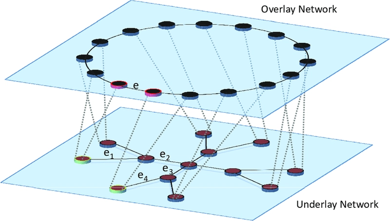
An Overlay Network
is a virtual network built on top of an existing network (for example, the Internet). It logically "overlaps" with the underlying network, using its infrastructure for data transmission. Nodes in the overlay network (computers, devices) communicate with each other using protocols other than those of the underlying network. The main purpose of overlay networks is to provide additional services, functions, or improvements to the existing capabilities of the underlying network, without the need to change its infrastructure.
Underlay Network (Basic Network)
The physical infrastructure (cables, routers, providers) that provides connectivity. The basis on which the overlay is built.
**"e” and “e1, e2, e3, e4": These labels probably represent various elements (e.g. devices, connections, nodes) illustrating the relationship between the overlay and the underlying network. They show the correspondence between the overlay's logical connections and the underlying network's physical connections.
In a structured peer-to-peer architecture, the overlay network is constructed
using a deterministic procedure. By far the most-used procedure is to organize the
processes through a distributed hash table (DHT).
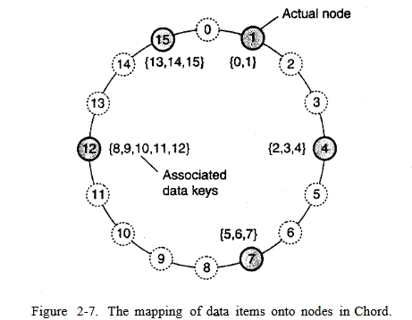
The image shows a visualization of the Chord Distributed Hash table (DHT). This is an illustration of a structured overlay network. Here's what it shows:
- Circle: Represents a logical ring in which network nodes are located.
- Nodes: Each point on the circle represents a node of the network. Shaded nodes are "active nodes" (Actual node). Unpainted ones are potential nodes.
- Node labels: Each node is assigned a unique identifier (from 0 to 15). These identifiers are used to determine the location of the data.
- Associated Data Keys: Each active node has a range of data keys stored on that node. For example, node 12 stores data with keys 8, 9, 10, 11, and 12. This shows how the data is distributed between the nodes. In the Chord network, data with the key "k" is stored on the first node, which follows the "k" clockwise. That is, if we are looking for data with key 9, we will find it on node 12.
DHT is characterized by the following properties:
Decentralization: a form of a system of collective nodes without coordination;
Scalability: the system will function equally efficiently with thousands or millions of nodes.;
Fault tolerance: The system will be equally reliable (in a sense) even if nodes are constantly connecting, disconnecting, or giving errors.
DHT Chord (Chord Distributed Hash Table) is a specific implementation of a distributed hash table (DHT) used in computer networks for organizing and storing data. DHT allows you to distribute information across multiple nodes in a network, providing efficient search and access to data.
Here are the key points about DHT Chord:
- DHT (Distributed Hash Table):
- Is a distributed database that stores key-value pairs.
- Keys and values are distributed among multiple network nodes.
- The main task is to search for a node that stores data using a given key.
- Chord:
- Specific DHT, organized as a logical ring.
- The network nodes are located in a ring, and each node is assigned a unique identifier (key).
- The data also has keys that determine which node it should be stored on.
- Routing: Each node knows about some other nodes in the network (the successors) and uses this information to efficiently route requests to the desired node storing the data.
- Stability: Chord provides a high degree of fault tolerance and dynamic node addition/removal without data loss (through the use of stabilization algorithms).
How Chord works:
-
Keys and identifiers:
- Each node of the network is assigned a unique identifier, which is usually the hash value of an IP address or other unique parameter.
- Each data element (for example, a file) is assigned a unique key, which is also a hash value.
-
Location of data:
- Data with the key "k" is stored on the first node, whose key is greater than or equal to "k" clockwise in the ring.
- Data search:
- When a node wants to find data on the key "k", it forwards the request to the nearest node, which stores this key (or knows, where this key is located).
- Nodes use the "successor" table to route requests.
- The request progresses through the ring until it reaches the node that stores the data.
Advantages of Chord:
- Scalability: Easily scaled, as the load is distributed between nodes.
- Failure tolerance: Failure of one node does not lead to complete data loss, as data is replicated on neighboring nodes.
- Effective search: Data retrieval is fast, as requests are routed along the optimal path.
Disadvantages of Chord:
- Complexity of implementation: More complex than some other DHTs.
- Setup and support: Requires specific configuration and maintenance.
- Delays: If there are a large number of nodes, it may take several hops to route the request.
Examples of using Chord:
- Data storage systems: Chord is used in distributed data storage systems.
- P2P networks: It was used in early file-sharing networks (for example, CFS - Cooperative File System).
- Other distributed applications: In various distributed systems where it is necessary to store and receive key data.

(this diagram shows an example of a distributed file system using Chord DHT for organizing and accessing data)

How it works (in simple words):
- When node 0 wants to find data belonging to, for example, node 16, it does not go around all nodes in a circle.
- Instead, it uses its “finger table” to quickly jump to nodes that are closer to the target.
- He can start by jumping 8 nodes (to node 8), then 4 nodes (to node 12), and so on until he reaches node 16.
The key difference from the previous example:
- The previous diagram showed where the data is stored in Chord (association of data keys with nodes).
- This diagram shows how to quickly find the right node in the Chord network.
- Chord routing uses "finger tables" and steps in the form of powers of two to efficiently route requests.
Using the finger table and power-of-two jumps allows DHT Chord to significantly speed up data retrieval.
**rather, each node will maintain shortcuts to other
nodes in such a way that lookups can generally be done in O(log (N) number of
steps, where N is the number of nodes participating in the overlay
Now consider Chord again.
- When a node wants to join the system, it starts with generating a random identifier id.
- Note that if the identifier space is large enough, then provided the random number generator is of good quality, the probability of generating an identifier that is already assigned to an actual node is close to zero.
- Then, the node can simply do a lookup on id, which will return the network address of succiid).
- At that point, the joining node can simply contact succiid) and its predecessor and insert itself in the ring.
- Of course, this scheme requires that each node also stores information on its predecessor. Insertion also yields that each data item whose key is now associated with node id, is transferred from succiid).
- Leaving is just as simple: node id informs its departure to its predecessor and successor, and transfers its data items to succ(id).
| Characteristic | Regular (Centralized) Network | DHT Chord (Decentralized) Network |
|---|---|---|
| Architecture | Central server(s) | Distributed, nodes store data and location information |
| Data storage | Centralized (on the server) | Distributed (on different network nodes) |
| Data retrieval | Request to the central server | Using DHT (routing algorithms) to find the node storing the data |
| Fault tolerance | Low (server failure = system failure) | High (data is replicated, the system continues to work) |
| Scalability | Limited (depends on server capacity) | High (adding new nodes increases capacity and performance) |
| Complexity | Easier (implementation of centralized components) | More complicated (requires implementation of distributed algorithms, routing) |
| Examples | Traditional databases (SQL, NoSQL), file servers | Chord, Kademlia, HDFS, Ceph, IPFS |
| Application in file systems | The server stores files, clients get access | DHT determines where to store data blocks, provides access to them |
| The main task | Storage and centralized access to data | Distributed storage and not dependent on a central server. |

CAN (Content-Addressable Network)
1. The general idea:
- Space: Data is stored in a multidimensional coordinate space (in the example, 2D: [0,1]x[0,1]).
- Nodes and Regions: Each node is responsible for a specific area of this space (region).
- Data assignment: Each data element is assigned a unique point in this space, which determines the owner node of the data.
2. Adding a node (P):
- Point selection: The new node P selects a random point in space.
- Region search: The system determines the node Q in which region this point is located.
- Division of the region: Node Q divides its area in half and gives one half to node P.
- Neighbors: Nodes are aware of their neighbors (nodes responsible for adjacent regions). 5.Data migration: The data that node P is now responsible for is being transferred from node Q.
3. Deleting a node:
- The problem: Deleting a node (for example, a node with coordinates (0.6, 0.7) in the figure) complicates the process, because a simple merging of regions can lead to irregular shapes of regions.
- Solution: A neighbor (for example, (0.9, 0.9)) takes over the area of the remote node and informs the neighbors about it.
- Rebalancing: To maintain symmetry and uniform distribution, the process of redistributing the entire space is periodically started.
Unstructured Peer-to-Peer Architecture (Unstructured P2P Networks)
1. The general idea:
- Randomized organization: Nodes interact with each other randomly.
- Random placement of data: The data is randomly distributed among the nodes.
- Search: When searching for data, the request is sent over the network (flood).
2. Membership Management:
- Partial View: Each node stores a list of "c" neighbors, which are selected more or less randomly.
- Information exchange: Nodes regularly exchange information about their neighbors (entries in the partial review).
- Two streams:
-
Active Stream: Initiates communication with another node by selecting it from its partial view. Sends information.
- Passive flow: Responds to requests by also forming a buffer with information about itself and other nodes.
- Creating a new partial review:
- *Information exchange: Nodes exchange information about their neighbors by combining their lists.
- Updating lists: Nodes create a new list of neighbors, either by exchanging information completely or by selecting old entries to delete.
Although it would seem that structured and unstructured peer-to-peer systems
form strict independent classes, this 'need actually not be case [see also Castro et
al. (2005)]. One key observation is that by carefully exchanging and selecting en-
tries from partial views, it is possible to construct and maintain specific topologies
of overlay networks. This topology management is achieved by adopting a two-
layered approach, as shown in Fig. 2-10.

Two-tier P2P architecture
1. Lower Level (Unstructured P2P):
- Task: Random graph support.
- Mechanism: Nodes periodically exchange records about neighbors (from the "partial review").
- Objective: To ensure that the "partial overview" contains information about randomly selected active nodes.
- Result: Create and maintain an up-to-date random network topology.
2. Upper level (Selection of the target topology):
- Getting information: Gets a "partial view" from the lower level.
- Additional selection: Selects nodes from the received list based on certain criteria (ranking function).
- Goal: To create a specific desired network topology (logical structure).
- Example:
-
Criteria: Nearest neighbors (distance between nodes).
- Action: Node P gradually generates a list of its nearest neighbors.
- Example: NxN Logical Grid:
-
Requirement: Each node must maintain a list of "c" nearest neighbors.
- Distance: d1 + d2, where d;=min(N-1ai-bil, lai-bil) is the distance between nodes (a1,a2) and (b1,b2).
- Operation: The lower level provides a random graph, while the upper level selects its nearest neighbors to build a logical grid.

Improvements and extensions in unstructured P2P networks
1. Semantic Proximity for efficient search:
- The idea: Use ranking functions that take into account the semantic proximity of the data.
- Goal: To create "semantic overlay networks" to improve search efficiency.
- Further discussion: It will be discussed in Chapter 5 in the context of attribute-based naming.
2. The problem of scalability and data retrieval:
- The problem: Data retrieval in growing unstructured networks is becoming problematic.
- Reason: Lack of deterministic routing (requests are mostly sent over the flood network).
-
Solutions:
- Flood limitation (to be discussed in Chapter 5).
- Using Superpeers.
3. Superpeers (Super Nodes):
- The idea: Special nodes that support the data index.
- Why: Help to solve the problem of scalability and improve search.
- Other scenarios: Useful in situations where resource coordination is necessary (for example, in a CDN content delivery network).
-
Examples:
- Data index: Nodes that store information about where the data is located.
- Brokers: Collect information about resource usage (for quick optimization of node selection).
- Superpeers Organization:
- Usually they themselves are organized in a P2P network (hierarchical structure).
- Regular nodes (clients) connect to their Superpeers.
- All communication of a regular node takes place through its Superpeer (see Fig. 2-12).

Detail: Superpeers and their role
1. Fixed client-superpeer connection:
- The principle: A regular node (client) joins superpeer when it enters the network and stays with it until it exits.
- Requirements: Superpeers must be long-lived and highly available.
- Accessibility Solutions: Backup schemes, for example, duplication of superpeers (clients connect to two).
2. Dynamic superpeer assignment:
- Fixed line restrictions: May not be optimal, for example, in file sharing networks.
- Alternative: The client can bind to superpeer, which has an index of files of interest to the client.
-
Dynamic change: The client can change the superpeer (Garbacki et al., 2005):
- Priority: The superpeer who returns the search result gets a preference.
3. Superpeer Selection:
- The problem: How do I select the nodes that will be superpeers?
- Connection with the problem of choosing a leader: This task is related to the task of choosing a leader, which will be discussed in Chapter 6.