


![[The AI Show Episode 145]: OpenAI Releases o3 and o4-mini, AI Is Causing “Quiet Layoffs,” Executive Order on Youth AI Education & GPT-4o’s Controversial Update](https://www.marketingaiinstitute.com/hubfs/ep%20145%20cover.png)


_Andreas_Prott_Alamy.jpg?width=1280&auto=webp&quality=80&disable=upscale#)


![Apple Ships 55 Million iPhones, Claims Second Place in Q1 2025 Smartphone Market [Report]](https://www.iclarified.com/images/news/97185/97185/97185-640.jpg)


DIY Smart home project: Presence-activated lights
Background I got these Antela smart bulbs a while ago. They connect to my home network, and I control them from my phone via either the Tuya Smart app (Tuya is a Chinese IoT service provider) or Google Home. I got the smart bulbs rather than smart switches because they allow me to customize the brightness and colour, a feature I found helpful when my eyes were super sensitive to light after surgery. I also recently began to use Home Assistant. Think of it as an open-source and more powerful alternative to Google Home/Amazon Alexa/Apple HomeKit/Samsung SmartThings. With those vendor platforms, you're limited to what they support. With Home Assistant, you can build your own setups and connect things as you wish, whether it's totally DIY or consumer-ready products from vendors. I recently got an idea for a project. In my typical daily workflow, I spend most time in my office and living room area, occasionally dashing to the bedroom to get something. I find it a minor annoyance having to stop to turn on the lights, so I wanted to have the bedroom lights turn on whenever I walked in. This means I need some sort of motion- or proximity-activated light. In the world of smart homes, there are always many different options. There are consumer-ready solutions, such as this light—plug it in, and that's all. When you come close, the light comes on. There are kits such as the Everything Presence One that only provide the sensor + networking functionality—plug it in, connect to your network, and it shows up as a device in your Home Assistant instance. From there, you can configure Home Assistant to turn on your lights based on the device state. I wanted to go a little more DIY. Instead of buying the presence sensor kit, I would build mine. My plan was to get an actual presence sensor element (such as this) and set that up to send data to Home Assistant, which can then control my lights. Schematic Here's the setup: The presence sensor detects human presence in an area. The microcontroller (physically wired to the sensor) powers the sensor and relays readings from it wirelessly to my Home Assistant instance (runnning elsewhere on a Raspberry Pi). Home Assistant turns on or off my lights when needed, depending on the readings from the sensor and my configured automation. Instead of manually programming the microcontroller, I'll run ESPHome on it, for two reasons: ESPHome is made by the makers of Home Assistant, so it already integrates with it ESPHome simplifies the programming so you can do everything with a few lines of YAML. No code required. Equipment For the microcontroller, I got an ESP32, specifically the ESP32-C3-DevKitM-1U (that's a mouthful!). The ESP32 naming convention still confuses me (somewhat helpful article and chips comparison), but here are my reasons: I got an ESP32 because I've seen it recommended a lot. It's small and cheap, easy to program to do "one thing". Other options could be the Raspberry Pi Pico W (which ESPHome also supports) and an Arduino (no idea about support). I got the C3 series because it has WiFi and ESPHome recommended it as the low-power version. I got the DevKit version because it comes with some conveniences for noobs: USB-to-serial converter, voltage regulator, GPIO pins already exposed, and reset & boot buttons. For the sensor, I got a passive infrared (PIR) sensor, Adafruit’s BS412. It has a great range of several meters, and is easy to wire. Aside: Active vs Passive IR sensors I initially got the Vishay TSSP93038SS1ZA infrared sensor, but this was a mistake. During testing, I realized that this is an active infrared sensor. It detects a source of IR light pulsating at a specific frequency, like an IR LED or a TV remote, which means it needs a dedicated IR emitter. Active IR systems are good for "light barriers": you have an emitter at one end and the receiver at the other. When something blocks the beam coming from the emitter, you trigger something. This kind of system is used in elevator doors, automatic taps, soap dispensers, towel dispensers, hand dryers, item counters on conveyor belts etc. But it wouldn’t work well for my desired setup; I need to sense the presence of a human within a given area (not only in a straight line). PIR sensors detect natural radiation of the human body, and are a better fit for the presence sensing application. A light barrier simply detects when the light source is interrupted. Source A presence sensor has a wider, 3D detection area, and works by sensing the IR radiation from humans. Source Getting used to the ESP32 and the sensor From here, I could jump straight to installing ESPHome on the ESP32 and configuring it. But of course I had to first program it manually and test some basic behaviour. There are multiple ways to program an ESP32, such as with Python or via the Arduino IDE, but I followed Espressif's Getting Started guide, which uses their official C framew

Background
I got these Antela smart bulbs a while ago. They connect to my home network, and I control them from my phone via either the Tuya Smart app (Tuya is a Chinese IoT service provider) or Google Home. I got the smart bulbs rather than smart switches because they allow me to customize the brightness and colour, a feature I found helpful when my eyes were super sensitive to light after surgery.
I also recently began to use Home Assistant. Think of it as an open-source and more powerful alternative to Google Home/Amazon Alexa/Apple HomeKit/Samsung SmartThings. With those vendor platforms, you're limited to what they support. With Home Assistant, you can build your own setups and connect things as you wish, whether it's totally DIY or consumer-ready products from vendors.
I recently got an idea for a project. In my typical daily workflow, I spend most time in my office and living room area, occasionally dashing to the bedroom to get something. I find it a minor annoyance having to stop to turn on the lights, so I wanted to have the bedroom lights turn on whenever I walked in.
This means I need some sort of motion- or proximity-activated light. In the world of smart homes, there are always many different options. There are consumer-ready solutions, such as this light—plug it in, and that's all. When you come close, the light comes on. There are kits such as the Everything Presence One that only provide the sensor + networking functionality—plug it in, connect to your network, and it shows up as a device in your Home Assistant instance. From there, you can configure Home Assistant to turn on your lights based on the device state.
I wanted to go a little more DIY. Instead of buying the presence sensor kit, I would build mine. My plan was to get an actual presence sensor element (such as this) and set that up to send data to Home Assistant, which can then control my lights.
Schematic
Here's the setup:
- The presence sensor detects human presence in an area.
- The microcontroller (physically wired to the sensor) powers the sensor and relays readings from it wirelessly to my Home Assistant instance (runnning elsewhere on a Raspberry Pi).
- Home Assistant turns on or off my lights when needed, depending on the readings from the sensor and my configured automation.
Instead of manually programming the microcontroller, I'll run ESPHome on it, for two reasons:
- ESPHome is made by the makers of Home Assistant, so it already integrates with it
- ESPHome simplifies the programming so you can do everything with a few lines of YAML. No code required.
Equipment
For the microcontroller, I got an ESP32, specifically the ESP32-C3-DevKitM-1U (that's a mouthful!). The ESP32 naming convention still confuses me (somewhat helpful article and chips comparison), but here are my reasons:
- I got an ESP32 because I've seen it recommended a lot. It's small and cheap, easy to program to do "one thing". Other options could be the Raspberry Pi Pico W (which ESPHome also supports) and an Arduino (no idea about support).
- I got the C3 series because it has WiFi and ESPHome recommended it as the low-power version.
- I got the DevKit version because it comes with some conveniences for noobs: USB-to-serial converter, voltage regulator, GPIO pins already exposed, and reset & boot buttons.
For the sensor, I got a passive infrared (PIR) sensor, Adafruit’s BS412. It has a great range of several meters, and is easy to wire.
Aside: Active vs Passive IR sensors
I initially got the Vishay TSSP93038SS1ZA infrared sensor, but this was a mistake. During testing, I realized that this is an active infrared sensor. It detects a source of IR light pulsating at a specific frequency, like an IR LED or a TV remote, which means it needs a dedicated IR emitter.
Active IR systems are good for "light barriers": you have an emitter at one end and the receiver at the other. When something blocks the beam coming from the emitter, you trigger something. This kind of system is used in elevator doors, automatic taps, soap dispensers, towel dispensers, hand dryers, item counters on conveyor belts etc. But it wouldn’t work well for my desired setup; I need to sense the presence of a human within a given area (not only in a straight line). PIR sensors detect natural radiation of the human body, and are a better fit for the presence sensing application.
 A light barrier simply detects when the light source is interrupted. Source
 A presence sensor has a wider, 3D detection area, and works by sensing the IR radiation from humans. Source
Getting used to the ESP32 and the sensor
From here, I could jump straight to installing ESPHome on the ESP32 and configuring it. But of course I had to first program it manually and test some basic behaviour. There are multiple ways to program an ESP32, such as with Python or via the Arduino IDE, but I followed Espressif's Getting Started guide, which uses their official C framework, ESP-IDF.
I did get stuck a few times, but nothing too serious. The only other microcontroller I've programmed is the Raspberry Pi Pico Zero, and that was much easier, because the it uses Python and has simpler guide docs. I'm new to ESP32, and it seems more powerful but more complex. ESP-IDF is in C and has fewer beginner guides.
It also took me a while to find the right pinout diagram, but it helped that the ESP32 had labels on the actual board (DevKit feature?).
To connect the BS412 to the ESP32, I followed the product page and datasheet [PDF]: pin 1 and 2 to GND (ground), pin 3 to 3.3V, and pin 4 (output) to a GPIO pin. (If you have trouble identifying which pin is which, there's a tiny tab on the sensor's head. Check the datasheet for the cross-section of the circular head to see the numbering of each pin relative to the tab.)

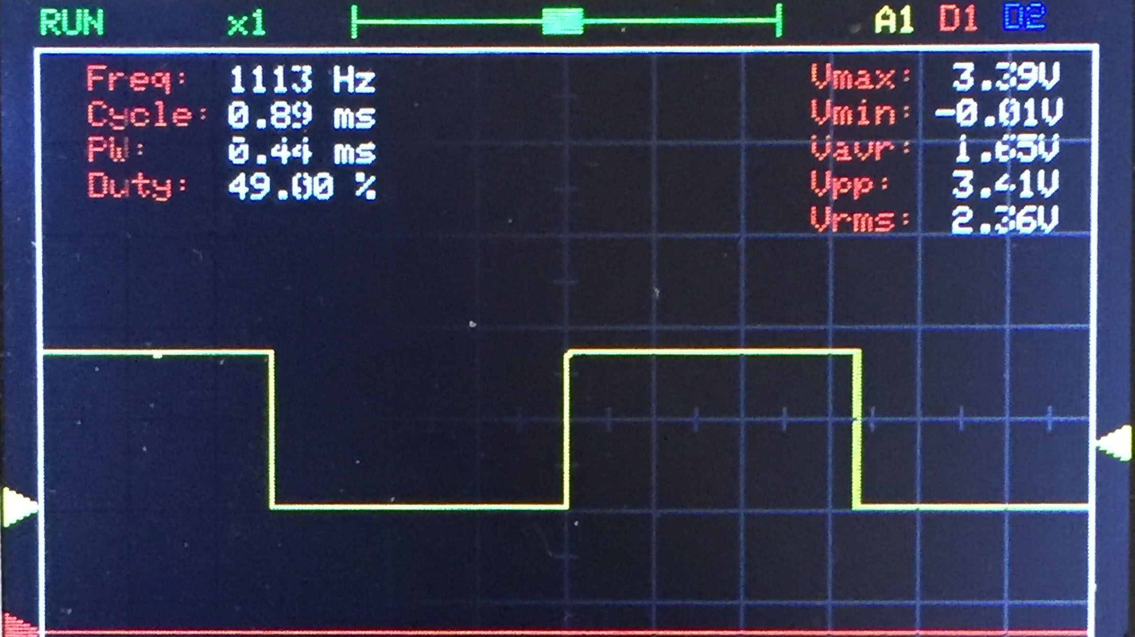
I also connected a LED to another GPIO as an indicator (note: this isn't necessary, since the DevKit comes with an RGB LED on GPIO8). Then I wrote an IDF program to read its value and light the LED. Interestingly, the PIR sensor has a HIGH output when it detects motion, different from the active IR sensor, which has LOW output when it detects an IR signal.
#include Aaaand this works. Nice.
Tuning the sensor
Now we begin to tweak and configure it so it works how we want.
The key sensor parameter to be tuned is the on-time, the length of time the signal stays HIGH after detecting motion. There's also a lock time, which is a minimum amount of time the signal will stay LOW before entering another HIGH phase.
The sensor works in phases:
- Motion detected → output goes HIGH and stays like this for at least the on-time
- Motion stops → after a short time (on-time exceeded), output goes LOW
- Lock time starts now → during this, no new detection possible
- After lock time ends → PIR is ready to detect again
Presence sensors are usually used in such phased setups: when a person enters the area, turn on the lights. Then turn them off if the person has not moved for a while. If the person is still in the area, they'll move and the lights will come back on.
The sensor's datasheet explains how to adjust the on-time, but the lock time is not configurable for this sensor. Luckily, it's small enough (2.3 seconds) that it doesn't matter. Adjusting the on-time is done by adjusting the potential difference between pin 2 and ground using a voltage divider setup, diagrammed below:

The datasheet has the recommended resistor values for the resistors in order to achieve different on-times. The shortest on-time is 2 seconds, which you get by connecting the pin directly to ground (0 V difference). The longest on-time is 1 hour (potential difference of 0.5 * the supply voltage). For my case, I wanted an on-time of around a minute, so I used a couple of resistors that added up to 310 kΩ as R2 (R1 is always 1 MΩ).

An alternate way to adjust the on-time is by not adjusting it, but using software to override the effect. You can add a delay in your programming, which is essentially implementing a state machine: when the sensor goes HIGH, your program sets its internal state to HIGH and keeps it that way until your desired on-time expires, ignoring any sensor changes during that time. I eventually switched to this. More on that later.
Switching to ESPHome
The next step: install ESPHome onto the microcontroller, and program it via ESPHome's YAML config. There are 3 stages to this (see Getting Started):
- Prerequisite: Install ESPHome Device Builder add-on in Home Assistant
- Install ESPHome on the microcontroller
- Configure the device to connect to your WiFi
- Add the device as a Home Assistant entity
The installation is mostly straightforward: plug it in via USB (if it has a serial-to-USB chip, which the DevKits do), and then use ESPHome Device Builder to flash it with the firmware (for which you'll likely be redirected to ESPHome Web).
I had trouble with this though. For anyone who runs into this in future (or myself), I'm documenting my issues and fixes in asides. Click to see the details.After running “Prepare for first use”, I kept getting “An error occurred. Improv Wi-Fi Serial not detected”. I think that ESPHome Web is supposed to use Improv WiFi to send my WiFi credentials to the newly flashed microcontroller, but somehow that was failing. I eventually found an alternative on the forums: the flashing process also turns my ESP32 into a temporary WiFi access point, and all I needed to do was connect to that, then visit the gateway address (highlighted below). That page showed me a form where I could enter the credentials for my home network, and that was done. From there, it turned off the AP, then took about 2 minutes before showing me a newly discovered device in ESPHome.


Once that is done, you should see the newly discovered device in ESPHome, from where you can "Take Control".

Taking control installs a basic ESPHome config onto the device, prompting you for some initial config such as a friendly name.
I ran into another issue here. It complained about the device not being able to connect to my WiFi, even though I had already done that in the previous step. I guess the WiFi configuration in ESPHome Web and ESPHome Device Builder are different, but I'm not sure why it didn't prompt me to add the WiFi credentials to the config first before trying to connect. The resolution for this was clicking "Edit" to edit the newly generated config YAML file, and then add a section containing my WiFi credentials ([docs](https://esphome.io/components/wifi.html\)\), then click "Save" and "Install".Finally, the device was successfully set up, and my device had a basic config:

Now time to configure my sensor. Here's what I added to the file at first:
binary_sensor:
  - platform: gpio
    pin: GPIO19
    device_class: occupancy
    name: "Bedroom Presence"
light:
  - platform: status_led
    name: "Presence detected"
    pin: GPIO10
This declares a Binary Sensor, a sensor which can be in one of two states (on/off). This component allows you to use any HIGH/LOW sensor without needing a custom integration for it. The occupancy device class tells Home Assistant how to interpret the states.
The second section declares a Status LED. ESPHome automatically knows to use it as an indicator—turn it on when the sensor is on, and vice versa.
This is beautiful. A few lines of YAML and I had this working!
Automating with Home Assistant
The final piece was to hook it up with Home Assistant. To do this, I went to Home Assistant's Settings -> Devices. The newly added ESPHome device had been discovered, so I clicked Add, assigned it to my Bedroom, and we were ready.

I went to add the automation, and discovered Home Assistant already comes with an inbuilt automation for "Motion-activated lights". I tried to use this at first.

But this didn't match my use case, since I don't want to turn on the lights every time, just from the afternoon until when I go to bed. So I made mine instead. Two actually—one to turn on the lights when the sensor detects a person, and one to turn them off when the detection status clears. I set them up to only work from 1 pm to 12 am.


You could also do this with only one automation, but I found it easier to wrap my head around this.
And voila! It worked. But there's more...
Power issues and more tweaking
The next thing I tried to do was make this mobile. Powering microcontroller boards is always a challenge. Thus far, I had simply plugged it into an old USB charger, which delivered the 5V needed. But I wanted to try a different location for the sensor, so I wanted to see if I could power it off battery.
I connected a 9V battery to the GND and 5V inputs (the DevKits come with a voltage regulator that ensures the board only gets 5V), and this worked...for about 2 days, and then the battery was empty! That was unsettling. I thought microcontrollers were supposed to be energy-efficient? Well, it was time for me to do some more tuning and learning.

First, I got rid of the LED. It was only meant to be a temporary aid during development; no need to use that extra power.
I also ended up getting rid of the voltage divider setup and going back to the original circuit, where pin 2 was connected to ground, and on-time was the default 2s. Instead, I just added a delay in ESPHome.
binary_sensor:
  - platform: gpio
    pin: GPIO19
    device_class: occupancy
    name: "Bedroom Presence"
    filters:
      - delayed_off: 45s
I don't know if this saves a lot of battery, but I'm much happier with the software version of on-time. It makes the hardware connection simpler, it's easier to maintain and adjust, and it's much more flexible. (Alternatively, I could add this delay into the Home Assistant automation, but I preferred to have it as part of the device, so the state of the sensor always matched the state of the lights).
Still, I learnt (thanks to ChatGPT and forums) that the common 9V batteries are pretty bad for powering microcontrollers. Despite providing a large voltage, they have low capacity (~500–600 mAh), worse than a typical 1.5V AA battery. Additionally, some energy is wasted in the voltage regulator.
And that's when I learnt about sleep mode. ESP32 can go into sleep and be woken up after a certain time, a sensor, or a touch. ESPHome supports this via the Deep Sleep component.
I only needed the sensor to be active from 1 pm to 1 am, so there was no point keeping it awake outside of that time. I experimented with things, and ended up adding a config like this:
deep_sleep:
  id: deep_sleep_1
  sleep_duration: 12h

time:
  - platform: sntp
    id: sntp_time_1
    timezone: "Europe/Berlin"
    on_time:
      # At 01:01 pm every day, block deep sleep
      - seconds: 0
        minutes: 1
        hours: 13
        then:
          - deep_sleep.prevent: deep_sleep_1
      # At 01:01 am every day, enter deep sleep
      - seconds: 0
        minutes: 1
        hours: 1
        then:
          - deep_sleep.allow: deep_sleep_1
          - deep_sleep.enter:
              id: deep_sleep_1
              until: "13:00:00"
              time_id: sntp_time_1
There are three parts here:
- A
deep_sleepconfiguration to sleep for 12 hours, calleddeep_sleep_1 - An
on_timetrigger that entersdeep_sleep_1at 1 am every day (I gave a buffer of +1 minute). - An
on_timetrigger that blocks deep sleep at 1 pm every day.
As long as my controller remains on, it will switch in and out of deep sleep at these times. But since sometimes I may unplug or disconnect my device to work on it, it might not be on when the time trigger comes around. So I also added an on_boot trigger to check the time whenever the ESP32 is turned on, and enter deep sleep if needed.
esphome:
  # ...
  on_boot:
    then:
      - delay: 1min
      - if:
          condition:
            and:
              - time.has_time
              - lambda: "return id(sntp_time_1).now().hour >= 13;"
          then:
            - logger.log: "It is past 1pm. Sensor activated."
            - deep_sleep.prevent: deep_sleep_1
          else:
            - logger.log: "It is not yet 1pm. Entering deep sleep."
            - deep_sleep.allow: deep_sleep_1
            - deep_sleep.enter:
                id: deep_sleep_1
                until: "13:00:00"
                time_id: sntp_time_1
The deep_sleep.prevent action (which blocks deep sleep) isn't really necessary in both triggers, but I kept it in there as a sort of failsafe.
As with most things here, there are multiple ways to achieve this configuration. This approach looks a little messy, but I found it relatively easy to reason about for me.
So now, when the time rolls around, or I plug in my ESP32 before 1 pm, I see logs like these:

It enters deep sleep and we can see that it has an "expected disconnect" from the ESPHome API. During this time, the device shows as "Unavailable" or "Unknown" in Home Assistant (although sometimes it just sticks on the last known state). And then when the wakeup time rolls around, it is able to reconnect:

Deep sleep is pretty cool. I'm still experimenting some more to see how long the battery lasts in this new setup.
Final thoughts

Finishing
At the end, the product still looks like a work in progress. It's on a breadboard, which is used for prototyping, and there are jumper wires everywhere. To make this a truly polished product, I could:
- move this from a breadboard to a custom PCB (printed circuit board)
- replace the DevKit with a regular ESP32, which is more energy-efficient
- make a custom case and mount for the whole thing (good use case for 3D printing)
However, these are secondary to my current goal, and I don't have the time to dedicate to them, so I'll move on for now.
Debugging and observability
A tricky thing about working with microcontrollers is debugging. In the initial development phase (when it's plugged in to your laptop and you're coding), it's easy, since you can log things to your console. But when it's out on its own, running in the wild, it's like a black box. The device might randomly stop working, and you have no idea why. Microcontollers are very tiny devices so they don't store logs, which means you'll never know what exactly happened in the past. You can only connect to your laptop and try to reproduce it.
Using a LED as an indicator to show the current state is a tiny help. A thing I want to try in future is having the ESP32 wirelessly send logs to another device, then having that device store the logs.
Buying parts
A surprising challenge here was figuring out the best place to get parts (cost and speed).
I started with Conrad (also because they have a store near me), but their selection is a bit limited and prices are higher (for example, an ESP32 DevKit costs €22). This is similar to what you get if you shop on Amazon.
Next up were European/German retailers like mouser.de, digikey.de, Distrelec, and Reichelt. These were super cheap (ESP32 DevKit for €9.31, and PIR sensor for €1.85), but had shipping times of around 5 days.
It turns out that most of these electronics parts come either from China or the US (and that's also probably from China). I considered going directly to AliExpress for maximum cost savings, but I find the site much harder to navigate, and the shipping would take even longer.
I ended up using Mouser. Shipping took around 4 days, but it took me 2 weeks to find time for the project again. That's the annoying thing about hardware development—when you don't have a part, you're forced to pause, and by the time the part arrives, you've switched contexts. This tweet is so accurate:
i’m just sitting here with like 6 stalled hardware projects waiting for physical components to arrive. yall live like this?
— yung perf papi (@ken_wheeler) April 8, 2025
### Credits
Thanks to Biodun for helping me understand some of my initial requirements and being a sounding board.