


![[The AI Show Episode 144]: ChatGPT’s New Memory, Shopify CEO’s Leaked “AI First” Memo, Google Cloud Next Releases, o3 and o4-mini Coming Soon & Llama 4’s Rocky Launch](https://www.marketingaiinstitute.com/hubfs/ep%20144%20cover.png)


![Is this too much for a modular monolith system? [closed]](https://i.sstatic.net/pYL1nsfg.png)


_Andreas_Prott_Alamy.jpg?width=1280&auto=webp&quality=80&disable=upscale#)


![What features do you get with Gemini Advanced? [April 2025]](https://i0.wp.com/9to5google.com/wp-content/uploads/sites/4/2024/02/gemini-advanced-cover.jpg?resize=1200%2C628&quality=82&strip=all&ssl=1)


![Apple Shares Official Trailer for 'Long Way Home' Starring Ewan McGregor and Charley Boorman [Video]](https://www.iclarified.com/images/news/97069/97069/97069-640.jpg)
![Apple Watch Series 10 Back On Sale for $299! [Lowest Price Ever]](https://www.iclarified.com/images/news/96657/96657/96657-640.jpg)
![EU Postpones Apple App Store Fines Amid Tariff Negotiations [Report]](https://www.iclarified.com/images/news/97068/97068/97068-640.jpg)
![Apple Slips to Fifth in China's Smartphone Market with 9% Decline [Report]](https://www.iclarified.com/images/news/97065/97065/97065-640.jpg)


How to Design a Wooden Spinning Lattoo Using 3D CAD Software
How to Design a Wooden Spinning Lattoo Using 3D CAD Software The wooden spinning lattoo, a traditional toy known for its simple charm and dynamic motion, is a great example of how cultural objects can be brought to life through modern 3D modeling. Using SelfCAD, a beginner-friendly yet powerful modeling tool, you can recreate this nostalgic item digitally with precision and creativity. The lattoo's smooth curves, central axis, and pointed base make it an ideal project for practicing symmetry, shaping, and detailing in 3D design. In this article, we will guide you through the process of designing a wooden spinning lattoo using SelfCAD’s core tools. From creating the basic outline to adding realistic textures and shaping the tip, each step will show how digital tools can simulate the craftsmanship of traditional wooden toys. This project not only helps build modeling skills but also connects digital design with cultural storytelling To access the interactive tutorial to this article, check out; https://www.selfcad.com/tutorials/5uq2y1o5224114u6w5yb1j3k2h6u6o5y6gr2 Once you’ve launched the editor; From the generators category on the toolbar choose shape generator; Set top radius to 10, bottom radius to 3, number of edges to 62, height to 25 Click + button to add new segment; Set top radius to 30, bottom radius to 30, height to 30, bevel segment to 5, bevel level to 20 Click + button to add new segment; Set top radius to 10, bottom radius to 10, height to 75, bevel segment to 0, position y to 5 Tick the checkmark to finalize shape generator Click to activate edge selection; Click on the gear icon to open the advanced selection tools; set loop selection to true, click on highlighted edge to select loop from the object. click on highlighted edge to select loop from the object. click on highlighted edge to select loop from the object. From the modify category on the toolbar choose fillet; Set intensity to 3.7, level to 5. Tick the checkmark to finalize fillet Click to activate polygon selection; Click on highlighted region to select it; Click scale on the toolbar; Set x to 0.5, z to 0.5 Click ‘x’ to close transformation panel From the 3D Shapes category on the toolbar choose sphere; Set radius to 30, position y to 60. Tick the checkmark to finalize sphere From the right panel choose cube selection; Set back to 15, front to 45 Tick the checkmark to finalize cube selection Click inverse selection button to inverse selection; Click delete button to delete selected objects From the modify category on the toolbar choose add thickness; Set thickness to 5 Tick the checkmark to finalize add thickness Click on shape 1 to select it Click stitch & scoop on the toolbar; from the tool panel choose difference, choose chape 1 to subtract and set keep subtracted object to true Tick the checkmark to finalize difference From the 3D Shapes category on the toolbar choose sphere; Set radius to 25, horizontal segments to 50, vertical segments to 50, position y to 130. Tick the checkmark to finalize sphere Click on shape 1 to select it Click stitch & scoop on the toolbar; From the tool panel choose union. Tick the checkmark to finalize union From the 3D Shapes category on the toolbar choose cylinder; Set top radius to 1, Bottom radius to 1, position y to 95, rotation x to 90. Tick the checkmark to finalize cylinder Click on union 1 to select it Click stitch & scoop on the toolbar; from the tool panel choose difference, choose mesh 12 to subtract Tick the checkmark to finalize difference Click on difference 1 to select it. Click on difference 2 to deselect Click color picker button to change color of object; Click red Click ok Click on difference 1 to deselect it. Click on difference 2 to select Click color picker button to change color of object; Click magenta Click ok As you continue honing your design skills, remember that SelfCAD offers a wealth of resources to support your learning journey. To deepen your understanding and explore more advanced features, consider checking out the interactive tutorials (https://www.selfcad.com/tutorials) available on the SelfCAD website. The tutorials page provides a treasure trove of guides, tips, and tricks that cater to designers of all levels. More structured learning experience can also be accessed at the SelfCAD Academy (https://www.selfcad.com/academy/curriculum/), https://www.youtube.com/@3dmodeling101, and 3D Modeling 101 series (https://www.youtube.com/playlist?list=PL74nFNT8yS9DcE1UlUUdiR1wFGv9DDfTB). This comprehensive resource offers in-depth courses taught by industry experts, allowing you to master the intricacies of SelfCAD at your own pace
How to Design a Wooden Spinning Lattoo Using 3D CAD Software
The wooden spinning lattoo, a traditional toy known for its simple charm and dynamic motion, is a great example of how cultural objects can be brought to life through modern 3D modeling. Using SelfCAD, a beginner-friendly yet powerful modeling tool, you can recreate this nostalgic item digitally with precision and creativity. The lattoo's smooth curves, central axis, and pointed base make it an ideal project for practicing symmetry, shaping, and detailing in 3D design.
In this article, we will guide you through the process of designing a wooden spinning lattoo using SelfCAD’s core tools. From creating the basic outline to adding realistic textures and shaping the tip, each step will show how digital tools can simulate the craftsmanship of traditional wooden toys. This project not only helps build modeling skills but also connects digital design with cultural storytelling
To access the interactive tutorial to this article, check out; https://www.selfcad.com/tutorials/5uq2y1o5224114u6w5yb1j3k2h6u6o5y6gr2
Once you’ve launched the editor;
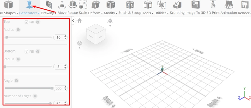
From the generators category on the toolbar choose shape generator; Set top radius to 10, bottom radius to 3, number of edges to 62, height to 25
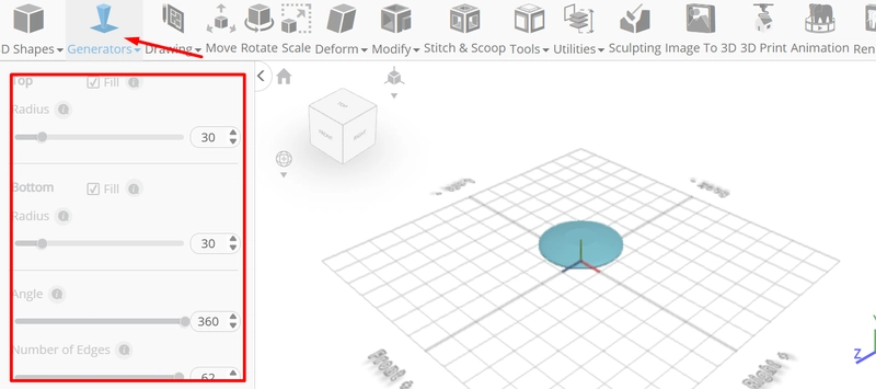
Click + button to add new segment; Set top radius to 30, bottom radius to 30, height to 30, bevel segment to 5, bevel level to 20
Click + button to add new segment; Set top radius to 10, bottom radius to 10, height to 75, bevel segment to 0, position y to 5
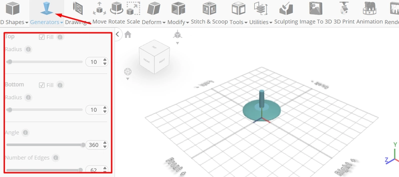
Tick the checkmark to finalize shape generator
Click to activate edge selection; Click on the gear icon to open the advanced selection tools; set loop selection to true, click on highlighted edge to select loop from the object.
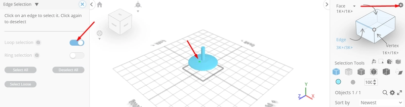
click on highlighted edge to select loop from the object.
click on highlighted edge to select loop from the object.
From the modify category on the toolbar choose fillet; Set intensity to 3.7, level to 5.
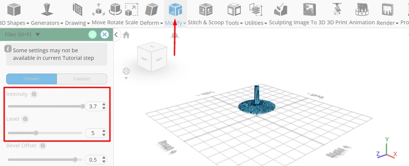
Tick the checkmark to finalize fillet
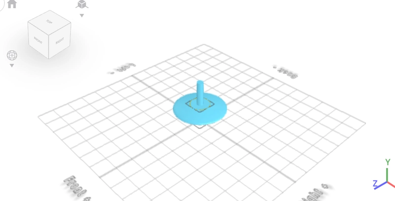
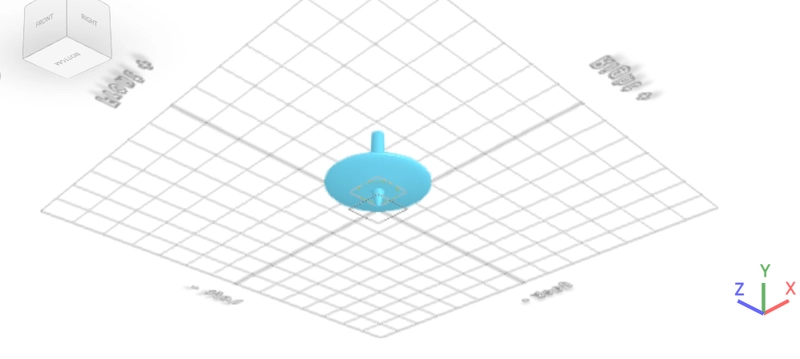
Click to activate polygon selection;
Click on highlighted region to select it; Click scale on the toolbar; Set x to 0.5, z to 0.5
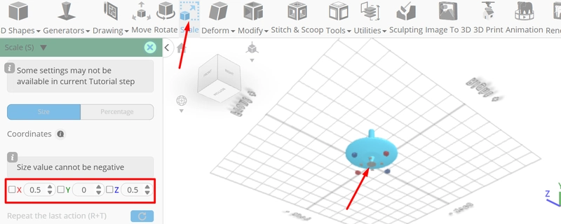
Click ‘x’ to close transformation panel
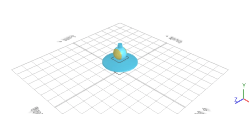
From the 3D Shapes category on the toolbar choose sphere; Set radius to 30, position y to 60.
Tick the checkmark to finalize sphere
From the right panel choose cube selection; Set back to 15, front to 45
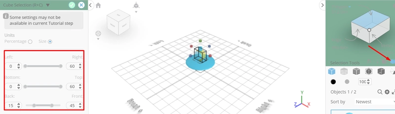
Tick the checkmark to finalize cube selection
Click inverse selection button to inverse selection; Click delete button to delete selected objects
From the modify category on the toolbar choose add thickness; Set thickness to 5
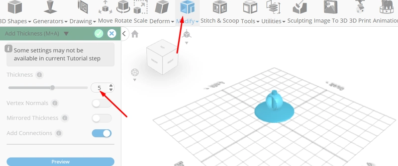
Tick the checkmark to finalize add thickness
Click on shape 1 to select it
Click stitch & scoop on the toolbar; from the tool panel choose difference, choose chape 1 to subtract and set keep subtracted object to true
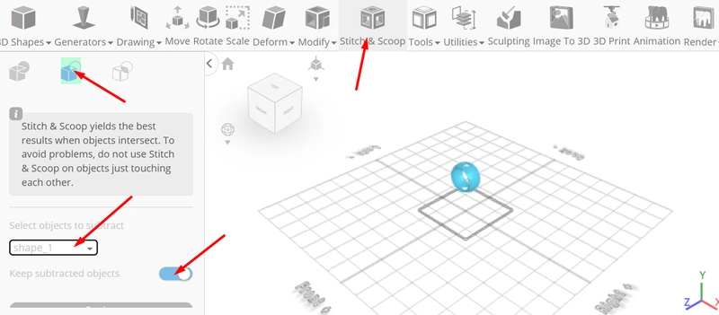
Tick the checkmark to finalize difference
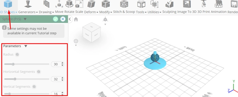
From the 3D Shapes category on the toolbar choose sphere; Set radius to 25, horizontal segments to 50, vertical segments to 50, position y to 130.
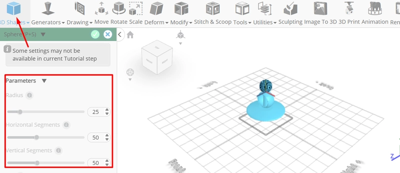
Tick the checkmark to finalize sphere
Click on shape 1 to select it
Click stitch & scoop on the toolbar; From the tool panel choose union.
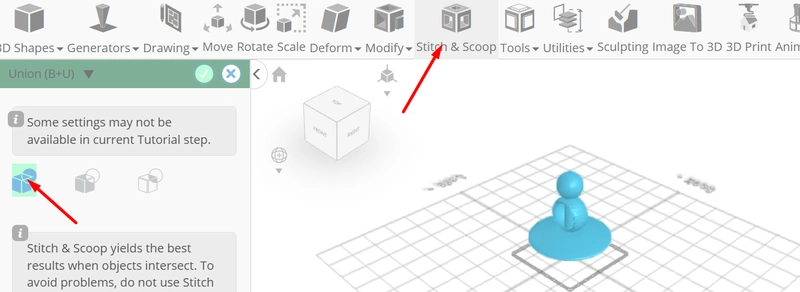
Tick the checkmark to finalize union
From the 3D Shapes category on the toolbar choose cylinder; Set top radius to 1, Bottom radius to 1, position y to 95, rotation x to 90.
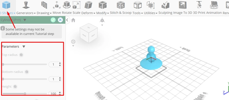
Tick the checkmark to finalize cylinder
Click on union 1 to select it
Click stitch & scoop on the toolbar; from the tool panel choose difference, choose mesh 12 to subtract
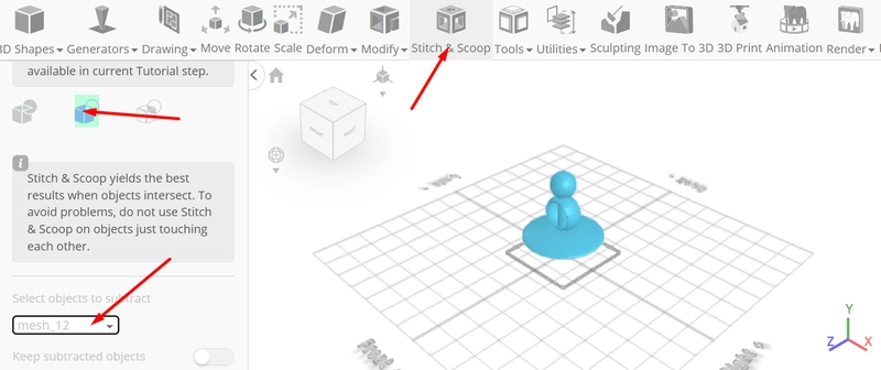
Tick the checkmark to finalize difference
Click on difference 1 to select it. Click on difference 2 to deselect
Click color picker button to change color of object; Click red
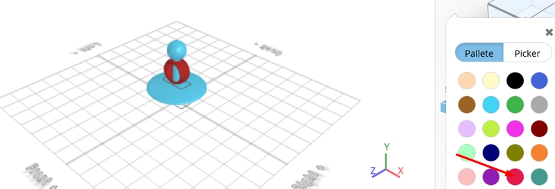
Click ok
Click on difference 1 to deselect it. Click on difference 2 to select
Click color picker button to change color of object; Click magenta
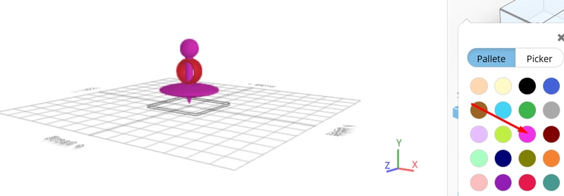
Click ok
As you continue honing your design skills, remember that SelfCAD offers a wealth of resources to support your learning journey. To deepen your understanding and explore more advanced features, consider checking out the interactive tutorials (https://www.selfcad.com/tutorials) available on the SelfCAD website. The tutorials page provides a treasure trove of guides, tips, and tricks that cater to designers of all levels.
More structured learning experience can also be accessed at the SelfCAD Academy (https://www.selfcad.com/academy/curriculum/), https://www.youtube.com/@3dmodeling101, and 3D Modeling 101 series (https://www.youtube.com/playlist?list=PL74nFNT8yS9DcE1UlUUdiR1wFGv9DDfTB). This comprehensive resource offers in-depth courses taught by industry experts, allowing you to master the intricacies of SelfCAD at your own pace
![Two-way bind a Signal Input object value with [(ngModel)]](https://media2.dev.to/dynamic/image/width=800%2Cheight=%2Cfit=scale-down%2Cgravity=auto%2Cformat=auto/https%3A%2F%2Fdev-to-uploads.s3.amazonaws.com%2Fuploads%2Farticles%2Fy8uorrbgpt7rqo9k76uf.png)