


![[The AI Show Episode 144]: ChatGPT’s New Memory, Shopify CEO’s Leaked “AI First” Memo, Google Cloud Next Releases, o3 and o4-mini Coming Soon & Llama 4’s Rocky Launch](https://www.marketingaiinstitute.com/hubfs/ep%20144%20cover.png)


![From fast food worker to cybersecurity engineer with Tae'lur Alexis [Podcast #169]](https://cdn.hashnode.com/res/hashnode/image/upload/v1745242807605/8a6cf71c-144f-4c91-9532-62d7c92c0f65.png?#)


![BPMN-procesmodellering [closed]](https://i.sstatic.net/l7l8q49F.png)


.jpg?#)
.jpg?#)


![CarPlay app with web browser for streaming video hits App Store [U]](https://i0.wp.com/9to5mac.com/wp-content/uploads/sites/6/2024/11/carplay-apple.jpeg?resize=1200%2C628&quality=82&strip=all&ssl=1)

![What’s new in Android’s April 2025 Google System Updates [U: 4/21]](https://i0.wp.com/9to5google.com/wp-content/uploads/sites/4/2025/01/google-play-services-3.jpg?resize=1200%2C628&quality=82&strip=all&ssl=1)


![Apple Releases iOS 18.5 Beta 3 and iPadOS 18.5 Beta 3 [Download]](https://www.iclarified.com/images/news/97076/97076/97076-640.jpg)
![Apple Seeds visionOS 2.5 Beta 3 to Developers [Download]](https://www.iclarified.com/images/news/97077/97077/97077-640.jpg)
![Apple Seeds tvOS 18.5 Beta 3 to Developers [Download]](https://www.iclarified.com/images/news/97078/97078/97078-640.jpg)
![Apple Seeds watchOS 11.5 Beta 3 to Developers [Download]](https://www.iclarified.com/images/news/97079/97079/97079-640.jpg)


How Implementing a Static Checker for Screen Specifications Led Us to Uncover Numerous Defects
I’m Kuniwak, a Software Engineer in Test. In this article I present a case study on developing a static checker for screen specifications (explained below). What I Want to Share Specification documents that describe screen layouts and transitions can be made machine‑readable. Once a specification is machine‑readable, static checking of the spec becomes possible. By running a static check we uncovered just under 40 defects across 15 % of the screens in my scope of responsibility. Machine‑readable specifications pave the way for further automation and reuse. Recap: What Is a Specification? There are several definitions of specification. Here, we treat a specification as the criterion that defines the correct behaviour of an implementation. When an implementation is judged correct, we say that the implementation satisfies the specification. Regardless of who performs the judgment, the result should be identical. Just as implementations can be faulty, specifications themselves can contain defects. If a specification erroneously flags behaviour that was intended to be correct—or the reverse—it is defective. A classic example is contradictory statements. If one part of the spec instructs the login‑screen button text to read “Login” while another says “Sign In”, no implementation can satisfy both simultaneously. A specification that no implementation can satisfy is worthless; evidently some behaviour was supposed to be accepted, but the spec rejects it. Another kind of defect (outside this article’s scope) arises when the spec is internally consistent yet the resulting correct implementation fails to solve the real‑world problem (e.g. sales targets are still missed). What Happens When a Specification Has Defects? In a development process the main consumers of a specification are: Implementers – responsible for delivering an implementation that satisfies the spec. Verifiers – responsible for confirming that the implementation satisfies the spec. If the specification is defective, both suffer: Unnecessary communication cost If implementers or verifiers notice something suspicious, they must raise questions before coding—communication that should have been unnecessary. Wasted implementation / verification cost If no one notices, code is written exactly as specified; the defect surfaces only when spec authors touch the system. Even if caught before release, some or all of that work is wasted. Loss of trust If the defect slips into production, end‑users discover it and confidence is lost in addition to wasted effort. In short: A specification is the yardstick for correct system behaviour. Specifications, like code, can contain defects. Defective specs cause extra cost and may damage trust. What Is a Screen Specification? This article deals with specs about the appearance of GUI screens and the transitions between them. Together we call these the screen specification, consisting of a screen‑display specification and a screen‑transition specification. A screen is (roughly) a set of application states grouped by identical GUI appearance 1. Take a typical login screen: the states formed by combinations of input‑form contents and server‑communication status collectively make up the login screen. For instance, if a service distinguishes general and privileged users, their login screens may look alike, yet the paths leading to them and subsequent destinations differ, so modelling them as separate screens is clearer. State transitions within a screen—or between screens—are triggered by events such as UI actions (click, hover, scroll), server messages, or simply time. Screen‑Display Specification Most screens place UI elements such as input forms and buttons at fixed positions. A screen‑display specification instructs, for each state, where each UI element appears and how it looks. Behaviour and state changes of individual UI elements are usually defined separately as a UI‑element specification, so shared widgets need not be duplicated across screens. In this article we assume the UI‑element spec already exists and the screen‑display spec describes: Layout – where each UI element sits, and Behaviour caused by interaction between UI elements. Interaction between UI elements means that an event changes multiple elements in concert 2. Example: an input form and a text label share a screen. On keyboard input, if the entry violates a rule, an error message appears in the label; otherwise the label is hidden—a textbook UI interaction. Example If element positions do not vary by state, a single screenshot suffices to show the layout. Where layouts differ by state, representative screenshots for each layout suffice. UI‑element interaction must be described in addition to the layout picture; in this case we use natural language, like the error‑message example above. An implementation is judge
I’m Kuniwak, a Software Engineer in Test.
In this article I present a case study on developing a static checker for screen specifications (explained below).
What I Want to Share
- Specification documents that describe screen layouts and transitions can be made machine‑readable.
- Once a specification is machine‑readable, static checking of the spec becomes possible.
- By running a static check we uncovered just under 40 defects across 15 % of the screens in my scope of responsibility.
- Machine‑readable specifications pave the way for further automation and reuse.
Recap: What Is a Specification?
There are several definitions of specification.
Here, we treat a specification as the criterion that defines the correct behaviour of an implementation.
When an implementation is judged correct, we say that the implementation satisfies the specification.
Regardless of who performs the judgment, the result should be identical.
Just as implementations can be faulty, specifications themselves can contain defects.
If a specification erroneously flags behaviour that was intended to be correct—or the reverse—it is defective.
A classic example is contradictory statements.
If one part of the spec instructs the login‑screen button text to read “Login” while another says “Sign In”, no implementation can satisfy both simultaneously.
A specification that no implementation can satisfy is worthless; evidently some behaviour was supposed to be accepted, but the spec rejects it.
Another kind of defect (outside this article’s scope) arises when the spec is internally consistent yet the resulting correct implementation fails to solve the real‑world problem (e.g. sales targets are still missed).
What Happens When a Specification Has Defects?
In a development process the main consumers of a specification are:
- Implementers – responsible for delivering an implementation that satisfies the spec.
- Verifiers – responsible for confirming that the implementation satisfies the spec.
If the specification is defective, both suffer:
-
Unnecessary communication cost
- If implementers or verifiers notice something suspicious, they must raise questions before coding—communication that should have been unnecessary.
-
Wasted implementation / verification cost
- If no one notices, code is written exactly as specified; the defect surfaces only when spec authors touch the system. Even if caught before release, some or all of that work is wasted.
-
Loss of trust
- If the defect slips into production, end‑users discover it and confidence is lost in addition to wasted effort.
In short:
- A specification is the yardstick for correct system behaviour.
- Specifications, like code, can contain defects.
- Defective specs cause extra cost and may damage trust.
What Is a Screen Specification?
This article deals with specs about the appearance of GUI screens and the transitions between them.
Together we call these the screen specification, consisting of a screen‑display specification and a screen‑transition specification.
A screen is (roughly) a set of application states grouped by identical GUI appearance 1.
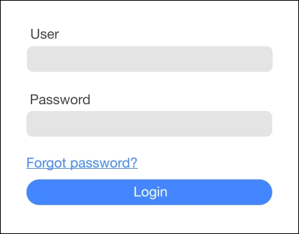
Take a typical login screen: the states formed by combinations of input‑form contents and server‑communication status collectively make up the login screen.
For instance, if a service distinguishes general and privileged users, their login screens may look alike, yet the paths leading to them and subsequent destinations differ, so modelling them as separate screens is clearer.
State transitions within a screen—or between screens—are triggered by events such as UI actions (click, hover, scroll), server messages, or simply time.
Screen‑Display Specification
Most screens place UI elements such as input forms and buttons at fixed positions.
A screen‑display specification instructs, for each state, where each UI element appears and how it looks.
Behaviour and state changes of individual UI elements are usually defined separately as a UI‑element specification, so shared widgets need not be duplicated across screens.
In this article we assume the UI‑element spec already exists and the screen‑display spec describes:
- Layout – where each UI element sits, and
- Behaviour caused by interaction between UI elements.
Interaction between UI elements means that an event changes multiple elements in concert 2.
Example: an input form and a text label share a screen.
On keyboard input, if the entry violates a rule, an error message appears in the label; otherwise the label is hidden—a textbook UI interaction.
Example
If element positions do not vary by state, a single screenshot suffices to show the layout.
Where layouts differ by state, representative screenshots for each layout suffice.
UI‑element interaction must be described in addition to the layout picture; in this case we use natural language, like the error‑message example above.
An implementation is judged to satisfy the screen‑display spec if, given the same event sequence, its appearance matches the spec in every state 3.
If they are non‑deterministic, each yields a set of possible appearances; the implementation passes when its set is included in the spec’s set.
If internal events exist, unstable states should be excluded. For client–server screens you usually want to expose communication events rather than hide them.
Screen‑Transition Specification
Most GUIs expect users to navigate through multiple screens.
We model a screen’s internal states as nodes and events as labelled directed edges, forming a graph called the screen‑transition specification.
For example, from state S_0 (empty user‑name/password fields) entering correct credentials Taro + password moves to S_Taro; we draw an edge labelled “input valid credentials for Taro” between those nodes 4.
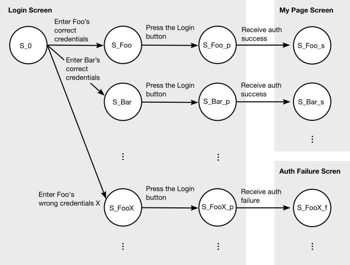
Common notations include state‑transition diagrams and tables.
Explaining how to judge conformance to this spec would be lengthy; our implementation relies on the theory of Communicating Sequential Processes (CSP).
For details, see the concept of refinement in CSP.
Making the Screen Spec Machine‑Readable
We started with existing Confluence pages written in Confluence wiki markup that lacked enough detail to serve as screen specs.
We rewrote each screen as a pair of:
- a UI‑element layout diagram (left below), and
- a UI‑element table (right below).
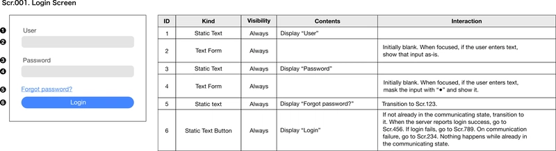
Scr.001 is the screen ID and Login Screen is the screen name.
Every screen is given an ID because other parts of the spec (e.g. the UI‑element table’s transition column) need to reference screens uniquely.
The left image is part of the screen‑display spec.
The right table records, for each UI element, its ID, type, display conditions, display content, and interactions.
Display conditions/content belong to the screen‑display spec; interactions belong to the screen‑transition spec.
Because the UI‑element table is plain wiki markup, our static checker can parse it to extract the transition graph.
State‑transition diagrams are drawn with a PlantUML macro so they remain machine‑readable.
Static Checking of Machine‑Readable Screen Specs
A machine‑readable spec enables static analysis.
We implemented a static checker (~6000 lines of Go) with 23 rules based on about 20 spec‑inspection viewpoints gathered in advance.
Here are a few examples (eight were automated):
-
Consistency between the transition diagram and UI‑element tables
- Each edge in the PlantUML diagram must appear in some table’s interaction column, and vice‑versa.
- Interaction description for interactive elements (buttons, check‑boxes, etc.).
- Explicit ordering for list‑type UI elements (look for the word “order” in the content column).
- Scaling instructions for dynamic images (“zoom in/out” or “crop” must appear when image size differs from its frame).
- …
However, a fully machine‑readable notation is not always human‑friendly, so we limited ourselves to natural‑language explanations in this case.
To avoid overlooking typos or omissions we added 15 auxiliary checks, e.g.:
- No duplicate IDs.
- The string
TODOmust not appear. - Text and images must specify whether they are static or dynamic.
- …
Implementation‑wise, each rule is a function that takes one of layout, element table or transition diagram and returns a list of detected defects, keeping rules independent and easy to add/remove.
Ignoring non‑applicable elements prevents imposing a single rigid format; richer notations (e.g. a flowchart for complex conditions) can coexist, and dedicated rules can be added later.
Results of Introducing Static Checking
Using this checker, we caught 40 defects across 15 % of the screens before the spec reached programmers.
After the checker flagged issues, the number of follow‑up questions about the spec was lower than in comparable projects without the checker.
Challenges of Machine‑Readable Screen Specs
Maintaining a machine‑readable spec turned out to be burdensome for non‑programmers, so the checker did not see continuous use.
Handing spec maintenance to developers might solve this, but then their effort must be justified—perhaps by automatically generating part of the implementation from the spec, as discussed next.
Applications of Machine‑Readable Specs
Making the screen spec and its surroundings machine‑readable allows parts of the specification process to be automated.
In our case, steps P3 and P4 of the process flow diagram were automated.
For P3, we linked layout diagrams to Figma objects and used the Figma API to refresh screenshots mechanically 5.
With a machine‑readable spec we could also auto‑generate parts of the implementation or of the test suite.
Complete generation may be hard, but partial generation is realistic.
For example, typical E2E tests exercise screen transitions; by adding element IDs to the transition spec, E2E tests could be generated automatically.
One could also imagine an MCP server that indexes and interprets machine‑readable specs for LLMs, aiding code generation, test generation, or other tasks.
Summary
- Specification documents describing screen layouts and transitions can be made machine‑readable.
- Machine‑readable specs enable static checking.
- Static checking uncovered nearly 40 defects across 15 % of the screens in my area.
- Machine‑readable specs open the door to further automation and reuse.
-
Even visually similar pages can be treated as separate screens. ↩
-
This parallels parallel composition in CSP. ↩
-
When both spec and implementation are deterministic and contain no internal events. ↩
-
For clarity, this diagram uses raw states and events. In practice it is cleaner to include state variables, guards and post‑conditions. ↩
-
Confluence’s Figma‑embed widget was too slow, so we avoided it. ↩

