


![[The AI Show Episode 142]: ChatGPT’s New Image Generator, Studio Ghibli Craze and Backlash, Gemini 2.5, OpenAI Academy, 4o Updates, Vibe Marketing & xAI Acquires X](https://www.marketingaiinstitute.com/hubfs/ep%20142%20cover.png)


![From drop-out to software architect with Jason Lengstorf [Podcast #167]](https://cdn.hashnode.com/res/hashnode/image/upload/v1743796461357/f3d19cd7-e6f5-4d7c-8bfc-eb974bc8da68.png?#)


.png?#)


_Christophe_Coat_Alamy.jpg?#)
 (1).webp?#)


![Apple Considers Delaying Smart Home Hub Until 2026 [Gurman]](https://www.iclarified.com/images/news/96946/96946/96946-640.jpg)
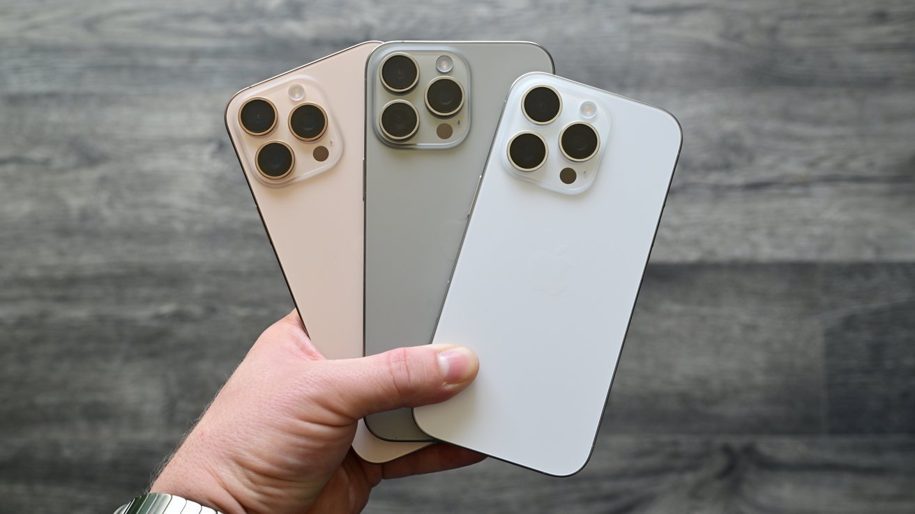
![iPhone 17 Pro Won't Feature Two-Toned Back [Gurman]](https://www.iclarified.com/images/news/96944/96944/96944-640.jpg)
![Tariffs Threaten Apple's $999 iPhone Price Point in the U.S. [Gurman]](https://www.iclarified.com/images/news/96943/96943/96943-640.jpg)


【电机控制器】LKS32MC037M6S8——UART、TIMER
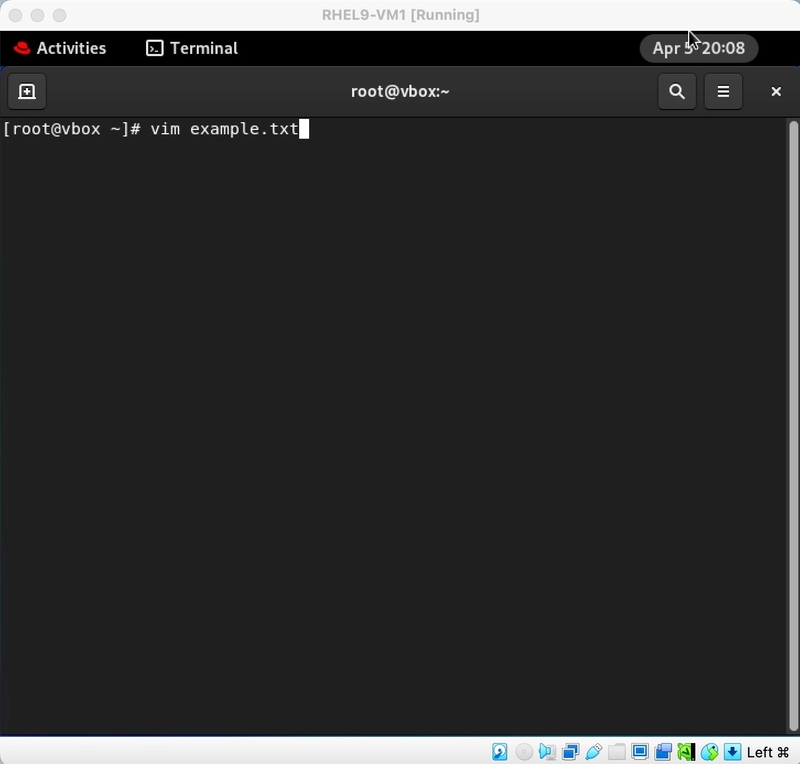
【电机控制器】LKS32MC037M6S8——UART @TOC 前言 使用工具: 1.JLINK仿真器——J-OB 2.USB-TTL 提示:以下是本篇文章正文内容,下面案例可供参考 一、接线 VCC——3.3 GND——GND SWDIO——SWDIO SWCLK——SWCLK 二、芯片手册 三、代码 void Timer1_Config(u16 Clk_Us) // { TIM_TimerInitTypeDef TIM_InitStruct; TIM_TimerStrutInit(&TIM_InitStruct); /* Timer结构体变量初始化 */ TIM_InitStruct.EN = ENABLE; /* 模块使能 */ TIM_InitStruct.TH = 48*Clk_Us; /* 设置计数器计数模值 1ms 1KHZ*/ TIM_InitStruct.CLK_DIV = TIM_Clk_Div1; /* 设置Timer模块数据分频系数 */ TIM_InitStruct.IE = TIM_IRQ_IE_ZC; TIM_TimerInit(TIMER1, &TIM_InitStruct); NVIC_SetPriority(TIMER1_IRQn, 2); NVIC_EnableIRQ(TIMER1_IRQn); /* enable the ADC0 interrupt */ } void GPIO_Config(void) { GPIO_InitTypeDef GPIO_InitStruct; GPIO_StructInit(&GPIO_InitStruct); GPIO_InitStruct.GPIO_Mode = GPIO_Mode_OUT; GPIO_InitStruct.GPIO_Pin = GPIO_Pin_1; GPIO_Init(GPIO0, &GPIO_InitStruct); /* P1.6-TX0, P1.7-RX0 UART0 */ GPIO_InitStruct.GPIO_Mode = GPIO_Mode_OUT; GPIO_InitStruct.GPIO_Pin = GPIO_Pin_5|GPIO_Pin_6; GPIO_Init(GPIO1, &GPIO_InitStruct); GPIO_InitStruct.GPIO_Mode = GPIO_Mode_IN; GPIO_InitStruct.GPIO_Pin = GPIO_Pin_7; GPIO_Init(GPIO1, &GPIO_InitStruct); GPIO_PinAFConfig(GPIO1, GPIO_PinSource_6, AF4_UART); //P1.6复用为UART_TX GPIO_PinAFConfig(GPIO1, GPIO_PinSource_7, AF4_UART); //P1.7复用为UART_RX } void Usart_Config(u32 BaudRate) { UART_InitTypeDef UART_InitStruct; UART_StructInit(&UART_InitStruct); UART_InitStruct.BaudRate = BaudRate; UART_InitStruct.WordLength = UART_WORDLENGTH_8b; UART_InitStruct.StopBits = UART_STOPBITS_1b; UART_InitStruct.FirstSend = UART_FIRSTSEND_LSB; UART_InitStruct.ParityMode = UART_Parity_NO; UART_InitStruct.IRQEna = 0; UART_Init(UART0, &UART_InitStruct); } 四、实验 五、参考文章 LKS32MC037M6S8用户手册 LKS32MC037M6S8芯片手册 基于LKS32MC03的全双工串口通信协议查询方式发送及接收例程 总结 本文仅仅简单介绍了【电机控制器】LKS32MC037M6S8——UART、TIMER,评论区欢迎讨论。
【电机控制器】LKS32MC037M6S8——UART
@TOC
前言
使用工具:
1.JLINK仿真器——J-OB
2.USB-TTL
提示:以下是本篇文章正文内容,下面案例可供参考
一、接线
VCC——3.3
GND——GND
SWDIO——SWDIO
SWCLK——SWCLK
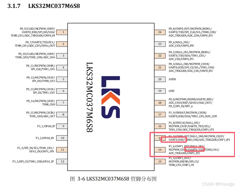
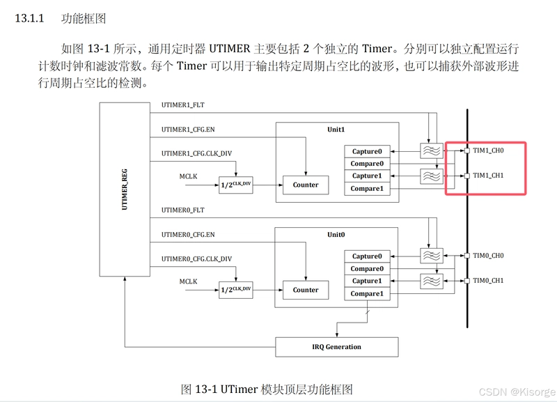
二、芯片手册
三、代码
void Timer1_Config(u16 Clk_Us)   //
{
        TIM_TimerInitTypeDef TIM_InitStruct;
    TIM_TimerStrutInit(&TIM_InitStruct);                                 /* Timer结构体变量初始化 */
      TIM_InitStruct.EN = ENABLE;                                          /* 模块使能 */
    TIM_InitStruct.TH = 48*Clk_Us;                                        /* 设置计数器计数模值 1ms 1KHZ*/
    TIM_InitStruct.CLK_DIV = TIM_Clk_Div1;                               /* 设置Timer模块数据分频系数 */
      TIM_InitStruct.IE = TIM_IRQ_IE_ZC;
    TIM_TimerInit(TIMER1, &TIM_InitStruct);

      NVIC_SetPriority(TIMER1_IRQn, 2);
        NVIC_EnableIRQ(TIMER1_IRQn);        /* enable the ADC0 interrupt */
}
void GPIO_Config(void)
{

        GPIO_InitTypeDef GPIO_InitStruct;
        GPIO_StructInit(&GPIO_InitStruct);

        GPIO_InitStruct.GPIO_Mode = GPIO_Mode_OUT;
        GPIO_InitStruct.GPIO_Pin =  GPIO_Pin_1;
        GPIO_Init(GPIO0, &GPIO_InitStruct);

        /* P1.6-TX0, P1.7-RX0  UART0 */
        GPIO_InitStruct.GPIO_Mode = GPIO_Mode_OUT;
        GPIO_InitStruct.GPIO_Pin =  GPIO_Pin_5|GPIO_Pin_6;
        GPIO_Init(GPIO1, &GPIO_InitStruct);

        GPIO_InitStruct.GPIO_Mode = GPIO_Mode_IN;
        GPIO_InitStruct.GPIO_Pin =  GPIO_Pin_7;
        GPIO_Init(GPIO1, &GPIO_InitStruct);

        GPIO_PinAFConfig(GPIO1, GPIO_PinSource_6, AF4_UART); //P1.6复用为UART_TX
        GPIO_PinAFConfig(GPIO1, GPIO_PinSource_7, AF4_UART); //P1.7复用为UART_RX
}
void Usart_Config(u32 BaudRate)
{
        UART_InitTypeDef UART_InitStruct;

        UART_StructInit(&UART_InitStruct);
        UART_InitStruct.BaudRate = BaudRate;
        UART_InitStruct.WordLength = UART_WORDLENGTH_8b;
        UART_InitStruct.StopBits = UART_STOPBITS_1b;
        UART_InitStruct.FirstSend = UART_FIRSTSEND_LSB;
        UART_InitStruct.ParityMode = UART_Parity_NO;
        UART_InitStruct.IRQEna = 0;
        UART_Init(UART0, &UART_InitStruct);

}
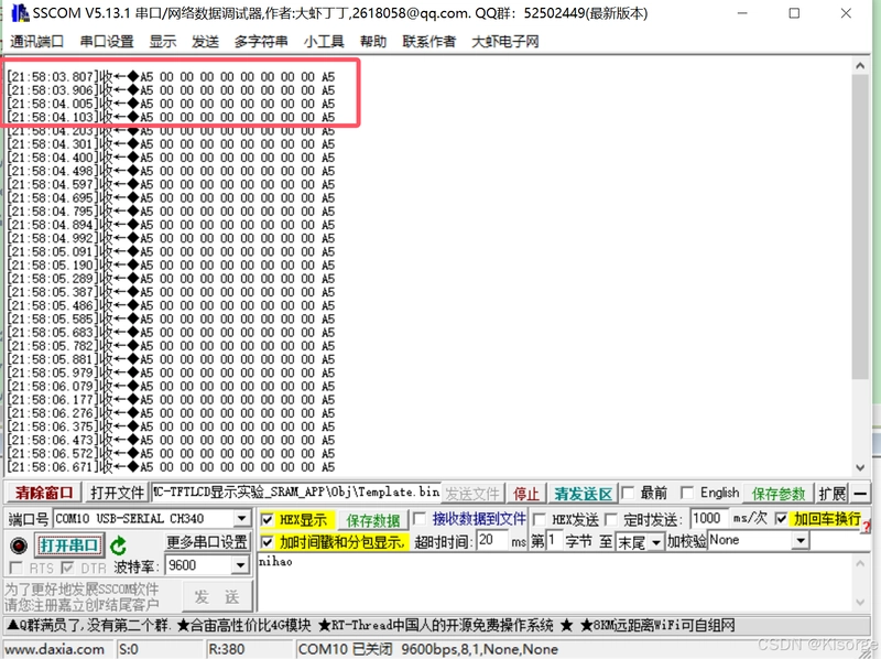
四、实验
五、参考文章
LKS32MC037M6S8用户手册
LKS32MC037M6S8芯片手册
基于LKS32MC03的全双工串口通信协议查询方式发送及接收例程
总结
本文仅仅简单介绍了【电机控制器】LKS32MC037M6S8——UART、TIMER,评论区欢迎讨论。
![[SQL] - Inner Join, Left Join, Non-Equi Join, Self Join](https://media2.dev.to/dynamic/image/width=800%2Cheight=%2Cfit=scale-down%2Cgravity=auto%2Cformat=auto/https%3A%2F%2Fdev-to-uploads.s3.amazonaws.com%2Fuploads%2Farticles%2Fm92uqxdtn6t3pwxuxu2i.png)