


![[The AI Show Episode 144]: ChatGPT’s New Memory, Shopify CEO’s Leaked “AI First” Memo, Google Cloud Next Releases, o3 and o4-mini Coming Soon & Llama 4’s Rocky Launch](https://www.marketingaiinstitute.com/hubfs/ep%20144%20cover.png)


![Blue Archive tier list [April 2025]](https://media.pocketgamer.com/artwork/na-33404-1636469504/blue-archive-screenshot-2.jpg?#)


.png?#)


-Baldur’s-Gate-3-The-Final-Patch---An-Animated-Short-00-03-43.png?width=1920&height=1920&fit=bounds&quality=70&format=jpg&auto=webp#)


![Nanoleaf Announces New Pegboard Desk Dock With Dual-Sided Lighting [Video]](https://www.iclarified.com/images/news/97030/97030/97030-640.jpg)

![Apple's Foldable iPhone May Cost Between $2100 and $2300 [Rumor]](https://www.iclarified.com/images/news/97028/97028/97028-640.jpg)
![Apple Releases Public Betas of iOS 18.5, iPadOS 18.5, macOS Sequoia 15.5 [Download]](https://www.iclarified.com/images/news/97024/97024/97024-640.jpg)


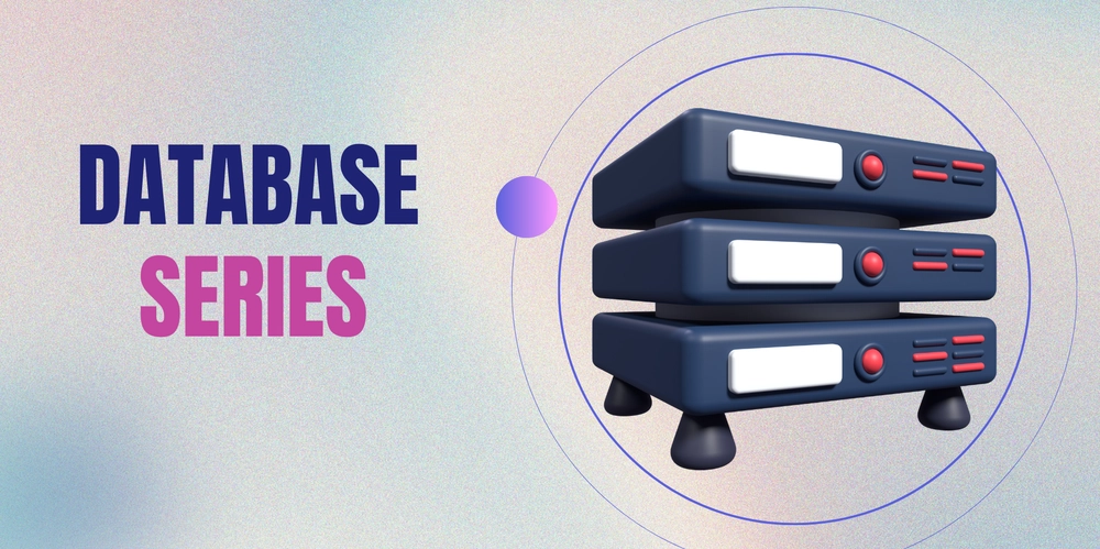
Entity-Relationship (ER) Diagrams: Visualizing Your Database Structure
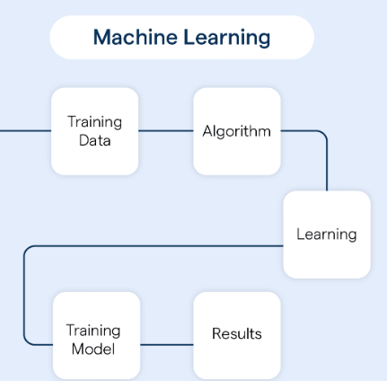
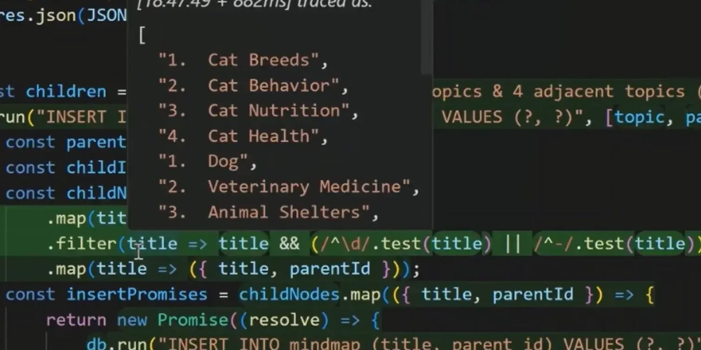
What is an ER Diagram? An Entity-Relationship (ER) Diagram is a visual representation of the entities in your database, their attributes, and the relationships between them. It serves as a blueprint for designing your database. Key Components of ER Diagrams Entities: Represent real-world objects or concepts (e.g., Users, Orders). Depicted as rectangles. Attributes: Describe the properties of an entity (e.g., Name, Email). Depicted as ovals connected to entities. Relationships: Show how entities are related (e.g., Users place Orders). Depicted as diamonds between entities. Example: Online Store ER Diagram Entities: Users (attributes: UserID, Name, Email) Orders (attributes: OrderID, OrderDate, Amount) Products (attributes: ProductID, ProductName, Price) Relationships: A User can place multiple Orders. An Order can contain multiple Products. [Users] -------- [Orders] -------- [Products] How to Design an ER Diagram Identify entities and their attributes. Define relationships and their cardinality (e.g., one-to-many, many-to-many). Normalize the structure to reduce redundancy. ER Diagram in Action Scenario: Design an ER Diagram for a Library System. Entities: Books, Members, Loans. Relationships: A Member can borrow multiple Books. Each Loan is associated with one Book and one Member. Example Attributes: Books: BookID, Title, Author. Members: MemberID, Name, Email. Loans: LoanID, LoanDate, ReturnDate. Challenge: Design Your Own ER Diagram Scenario: Create an ER Diagram for a University System with the following entities: Students: Includes StudentID, Name, and Major. Courses: Includes CourseID, CourseName, and Credits. Enrollments: Tracks which students are enrolled in which courses. Draw the relationships. Are they one-to-many or many-to-many? What attributes should be stored in each entity? Think About It Why are ER Diagrams a critical step before creating a database? How do you handle many-to-many relationships in an actual database schema?
What is an ER Diagram?
An Entity-Relationship (ER) Diagram is a visual representation of the entities in your database, their attributes, and the relationships between them. It serves as a blueprint for designing your database.
Key Components of ER Diagrams
-
Entities: Represent real-world objects or concepts (e.g., Users, Orders).
- Depicted as rectangles.
-
Attributes: Describe the properties of an entity (e.g., Name, Email).
- Depicted as ovals connected to entities.
-
Relationships: Show how entities are related (e.g., Users place Orders).
- Depicted as diamonds between entities.
Example: Online Store ER Diagram
-
Entities:
- Users (attributes: UserID, Name, Email)
- Orders (attributes: OrderID, OrderDate, Amount)
- Products (attributes: ProductID, ProductName, Price)
-
Relationships:
- A User can place multiple Orders.
- An Order can contain multiple Products.
[Users] ----< Places >---- [Orders] ----< Contains >---- [Products]
How to Design an ER Diagram
- Identify entities and their attributes.
- Define relationships and their cardinality (e.g., one-to-many, many-to-many).
- Normalize the structure to reduce redundancy.
ER Diagram in Action
Scenario: Design an ER Diagram for a Library System.
Entities: Books, Members, Loans.
-
Relationships:
- A Member can borrow multiple Books.
- Each Loan is associated with one Book and one Member.
Example Attributes:
- Books: BookID, Title, Author.
- Members: MemberID, Name, Email.
- Loans: LoanID, LoanDate, ReturnDate.
Challenge: Design Your Own ER Diagram
Scenario: Create an ER Diagram for a University System with the following entities:
- Students: Includes StudentID, Name, and Major.
- Courses: Includes CourseID, CourseName, and Credits.
- Enrollments: Tracks which students are enrolled in which courses.
- Draw the relationships. Are they one-to-many or many-to-many?
- What attributes should be stored in each entity?
Think About It
Why are ER Diagrams a critical step before creating a database?
How do you handle many-to-many relationships in an actual database schema?