


![[The AI Show Episode 144]: ChatGPT’s New Memory, Shopify CEO’s Leaked “AI First” Memo, Google Cloud Next Releases, o3 and o4-mini Coming Soon & Llama 4’s Rocky Launch](https://www.marketingaiinstitute.com/hubfs/ep%20144%20cover.png)


![From fast food worker to cybersecurity engineer with Tae'lur Alexis [Podcast #169]](https://cdn.hashnode.com/res/hashnode/image/upload/v1745242807605/8a6cf71c-144f-4c91-9532-62d7c92c0f65.png?#)


![BPMN-procesmodellering [closed]](https://i.sstatic.net/l7l8q49F.png)


.jpg?#)
.jpg?#)


![CarPlay app with web browser for streaming video hits App Store [U]](https://i0.wp.com/9to5mac.com/wp-content/uploads/sites/6/2024/11/carplay-apple.jpeg?resize=1200%2C628&quality=82&strip=all&ssl=1)
![What’s new in Android’s April 2025 Google System Updates [U: 4/21]](https://i0.wp.com/9to5google.com/wp-content/uploads/sites/4/2025/01/google-play-services-3.jpg?resize=1200%2C628&quality=82&strip=all&ssl=1)


![Apple Releases iOS 18.5 Beta 3 and iPadOS 18.5 Beta 3 [Download]](https://www.iclarified.com/images/news/97076/97076/97076-640.jpg)
![Apple Seeds visionOS 2.5 Beta 3 to Developers [Download]](https://www.iclarified.com/images/news/97077/97077/97077-640.jpg)
![Apple Seeds tvOS 18.5 Beta 3 to Developers [Download]](https://www.iclarified.com/images/news/97078/97078/97078-640.jpg)
![Apple Seeds watchOS 11.5 Beta 3 to Developers [Download]](https://www.iclarified.com/images/news/97079/97079/97079-640.jpg)


Developing a UARTLite Driver over XDMA (PCIe) on a Custom SDR Board (Bridging AXI IP to Linux via PCIe)
Abstract This project demonstrates how to connect an FPGA-based UARTLite peripheral to Linux user-space applications through PCIe XDMA. I implement a TTY interface (Linux TTY driver) /dev/ttyULx and show an alternative direct Python access using mmap. Ideal for integration into SDR, robotics, and embedded systems! What is the device? ➔ Our custom SDR board based on FPGA Artix-7, a GPS SIM68 module, and an AD9361 RF transceiver, featuring a PCIe interface for FPGA–Linux data exchange via XDMA. What will we do? ➔ Develop a Linux driver for UARTLite over XDMA and demonstrate an alternative method for direct access via Python. Why is this important? ➔ This solution enables easy integration of custom FPGA peripherals into Linux systems without complicated manual configuration, especially useful in SDR, robotics, autonomous systems, and IoT projects. 1. Introduction Embedded FPGA systems are widely used in Software-Defined Radio (SDR) applications. Effective communication between FPGA and CPU is critical but challenging when interfacing via PCIe. This article focuses on developing a driver for UARTLite over XDMA, showing two approaches: Linux kernel-space TTY and user-space direct access via Python. We aim to demonstrate the system architecture, driver implementation, and testing process on a custom SDR platform. Project highlights: ✅ Custom-designed SDR board with FPGA Artix-7 and AD9361 ✅ Host system: Latte Panda Sigma ✅ Built-in UARTLite connected to a GPS SIM68 module ✅ High-speed data transfer via PCIe XDMA ✅ Two operation modes: Linux TTY Driver interface (/dev/ttyULx) Direct Python access via XDMA and mmap 2. System Architecture 2.0 Board and Connections Overview The project is based on a fully custom SDR board with PCIe interface: Main components: Component Description FPGA Xilinx Artix-7 (XC7A200T) RF Transceiver Analog Devices AD9361 (70 MHz – 6 GHz) GPS Module SIM68 (NMEA 0183 Output) DDR Memory MT41K256M16HA-125 AAT Host Board LattePanda Sigma Interface PCIe Gen1 x4 (10 Gbps via M.2 connector) Data Path XDMA over AXI bus UART Peripheral AXI UARTLite IP Core (9600 baud) Form Factor M.2 2280 (80mm × 22mm) 2.1 System Block Diagram The diagram below illustrates the data flow chain between SIM68, UARTLite, XDMA, and the CPU: Data flow: SIM68 transmits NMEA messages over UART to UARTLite inside FPGA. UARTLite communicates with XDMA (PCIe DMA) via AXI bus. XDMA sends the data through PCIe to the CPU (LattePanda Sigma). CPU processes the data in user-space, communicating with the Linux kernel. Linux Kernel exposes a TTY device or Python API (/dev/ttyUL0). User Application interacts with the UART either via Python scripts or terminal. The second diagram shows direct Python access via XDMA without using the Linux driver: Data flow: SIM68 transmits NMEA messages over UART to UARTLite inside FPGA. UARTLite connects to XDMA over the AXI bus. XDMA transfers data over PCIe to the CPU. CPU maps /dev/xdma0_user into memory using mmap. Python Application directly accesses the UARTLite registers (RX FIFO / TX FIFO), bypassing the Linux kernel driver. Thus, the interaction occurs without using the standard Linux TTY driver, which allows: Minimizing system call overhead. Reducing CPU load by utilizing async IO. Rapidly prototyping and debugging FPGA-based systems. System Description The system consists of the following components and their interconnections: SIM68 (GPS Module) A GPS module that sends data over a UART interface. Connected to the UartLite (UART Controller) via UART. UartLite (UART Controller) A UART controller that receives data from the GPS module. Connected to XDMA (PCIe DMA) via the AXI bus. AXI UARTLite Product Guide (PG142) AXI Interconnect Product Guide (PG059) XDMA (PCIe DMA) A direct memory access (DMA) controller over PCIe. AXI PCIe DMA Product Guide (PG195) Connected to the CPU (Latte Panda Sigma) via PCIe. CPU (Latte Panda Sigma) The central processor that processes data received from XDMA. Communicates with the Linux Kernel from the User-space. Linux Kernel The operating system kernel running on the CPU. Provides interfaces for the User Application via TTY / Python. Linux TTY Documentation User Application A user-space application that interacts with the Linux Kernel to access the data, either through TTY devices or Python scripts. This architecture demonstrates how the driver manages communication with the UARTLite module. 2.2 Vivado Block Diagram The project uses XDMA (PCIe DMA Bridge). AXI Interconnect connects XDMA, AXI Register Slice, and AXI UARTLite. AXI UARTLite is mapped into the system via AXI Interconnect. AXI GPIO blocks are also available for additional control. Primary data path: FPGA → AXI Interconnect → AXI UARTLite → XDMA → CPU/Linux * Below is a screenshot of the Vivado project: or a simpler implementat
Abstract
This project demonstrates how to connect an FPGA-based UARTLite peripheral to Linux user-space applications through PCIe XDMA.
I implement a TTY interface (Linux TTY driver) /dev/ttyULx and show an alternative direct Python access using mmap.
Ideal for integration into SDR, robotics, and embedded systems!
What is the device?
➔ Our custom SDR board based on FPGA Artix-7, a GPS SIM68 module, and an AD9361 RF transceiver, featuring a PCIe interface for FPGA–Linux data exchange via XDMA.What will we do?
➔ Develop a Linux driver for UARTLite over XDMA and demonstrate an alternative method for direct access via Python.Why is this important?
➔ This solution enables easy integration of custom FPGA peripherals into Linux systems without complicated manual configuration, especially useful in SDR, robotics, autonomous systems, and IoT projects.
1. Introduction
Embedded FPGA systems are widely used in Software-Defined Radio (SDR) applications.
Effective communication between FPGA and CPU is critical but challenging when interfacing via PCIe.
This article focuses on developing a driver for UARTLite over XDMA, showing two approaches: Linux kernel-space TTY and user-space direct access via Python.
We aim to demonstrate the system architecture, driver implementation, and testing process on a custom SDR platform.
Project highlights:
✅ Custom-designed SDR board with FPGA Artix-7 and AD9361
✅ Host system: Latte Panda Sigma
✅ Built-in UARTLite connected to a GPS SIM68 module
✅ High-speed data transfer via PCIe XDMA
✅ Two operation modes:
-
Linux TTY Driver interface (
/dev/ttyULx) -
Direct Python access via XDMA and
mmap
2. System Architecture
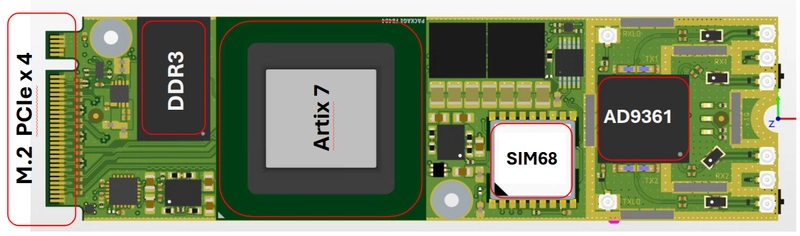
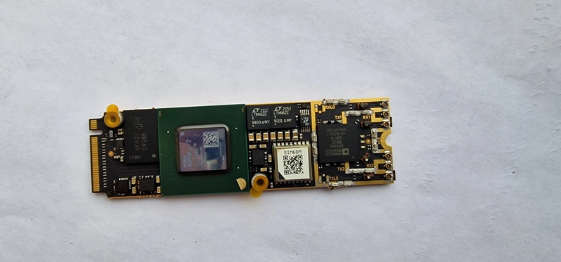
2.0 Board and Connections Overview
The project is based on a fully custom SDR board with PCIe interface:
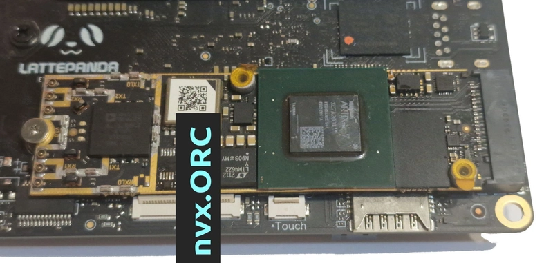
Main components:
| Component | Description |
|---|---|
| FPGA | Xilinx Artix-7 (XC7A200T) |
| RF Transceiver | Analog Devices AD9361 (70 MHz – 6 GHz) |
| GPS Module | SIM68 (NMEA 0183 Output) |
| DDR Memory | MT41K256M16HA-125 AAT |
| Host Board | LattePanda Sigma |
| Interface | PCIe Gen1 x4 (10 Gbps via M.2 connector) |
| Data Path | XDMA over AXI bus |
| UART Peripheral | AXI UARTLite IP Core (9600 baud) |
| Form Factor | M.2 2280 (80mm × 22mm) |
2.1 System Block Diagram
The diagram below illustrates the data flow chain between SIM68, UARTLite, XDMA, and the CPU:
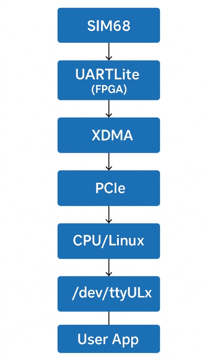
Data flow:
SIM68 transmits NMEA messages over UART to UARTLite inside FPGA.
UARTLite communicates with XDMA (PCIe DMA) via AXI bus.
XDMA sends the data through PCIe to the CPU (LattePanda Sigma).
CPU processes the data in user-space, communicating with the Linux kernel.
Linux Kernel exposes a TTY device or Python API (
/dev/ttyUL0).User Application interacts with the UART either via Python scripts or terminal.
The second diagram shows direct Python access via XDMA without using the Linux driver:
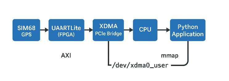
Data flow:
SIM68 transmits NMEA messages over UART to UARTLite inside FPGA.
UARTLite connects to XDMA over the AXI bus.
XDMA transfers data over PCIe to the CPU.
CPU maps
/dev/xdma0_userinto memory using mmap.Python Application directly accesses the UARTLite registers (RX FIFO / TX FIFO), bypassing the Linux kernel driver.
Thus, the interaction occurs without using the standard Linux TTY driver, which allows:
Minimizing system call overhead.
Reducing CPU load by utilizing async IO.
Rapidly prototyping and debugging FPGA-based systems.
System Description
The system consists of the following components and their interconnections:
SIM68 (GPS Module)
- A GPS module that sends data over a UART interface.
- Connected to the UartLite (UART Controller) via UART.
UartLite (UART Controller)
- A UART controller that receives data from the GPS module.
- Connected to XDMA (PCIe DMA) via the AXI bus.
- AXI UARTLite Product Guide (PG142)
- AXI Interconnect Product Guide (PG059)
XDMA (PCIe DMA)
- A direct memory access (DMA) controller over PCIe.
- AXI PCIe DMA Product Guide (PG195)
- Connected to the CPU (Latte Panda Sigma) via PCIe.
CPU (Latte Panda Sigma)
- The central processor that processes data received from XDMA.
- Communicates with the Linux Kernel from the User-space.
Linux Kernel
- The operating system kernel running on the CPU.
- Provides interfaces for the User Application via TTY / Python.
- Linux TTY Documentation
User Application
- A user-space application that interacts with the Linux Kernel to access the data, either through TTY devices or Python scripts.
This architecture demonstrates how the driver manages communication with the UARTLite module.
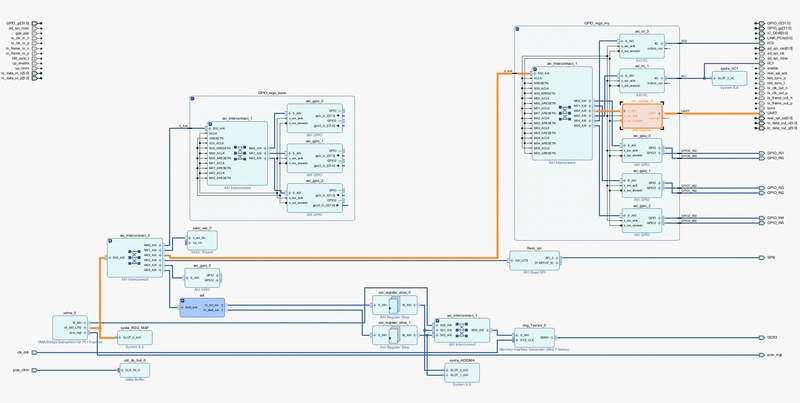
2.2 Vivado Block Diagram
The project uses XDMA (PCIe DMA Bridge).
AXI Interconnect connects XDMA, AXI Register Slice, and AXI UARTLite.
AXI UARTLite is mapped into the system via AXI Interconnect.
AXI GPIO blocks are also available for additional control.
Primary data path:
FPGA → AXI Interconnect → AXI UARTLite → XDMA → CPU/Linux
*
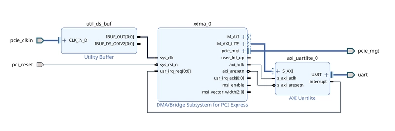
Below is a screenshot of the Vivado project:
or a simpler implementation focused only on UartLite:
2.3 XDMA and UartLite Configuration:
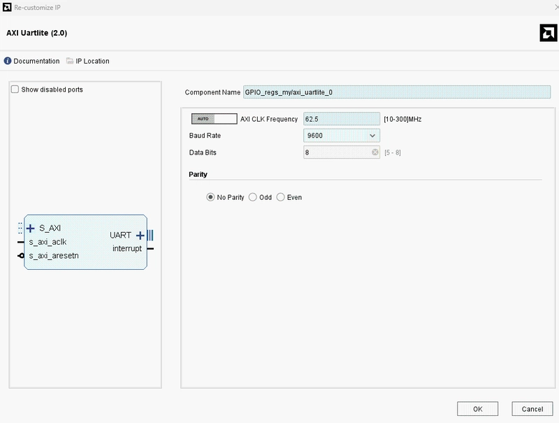
AXI UARTLite (IP Settings):
AXI Clock Frequency:
62.5 MHzUART Baud Rate:
9600 baudData Width:
8 bitsParity:
None (disabled)
(For higher speeds, 115200 baud can be configured.)
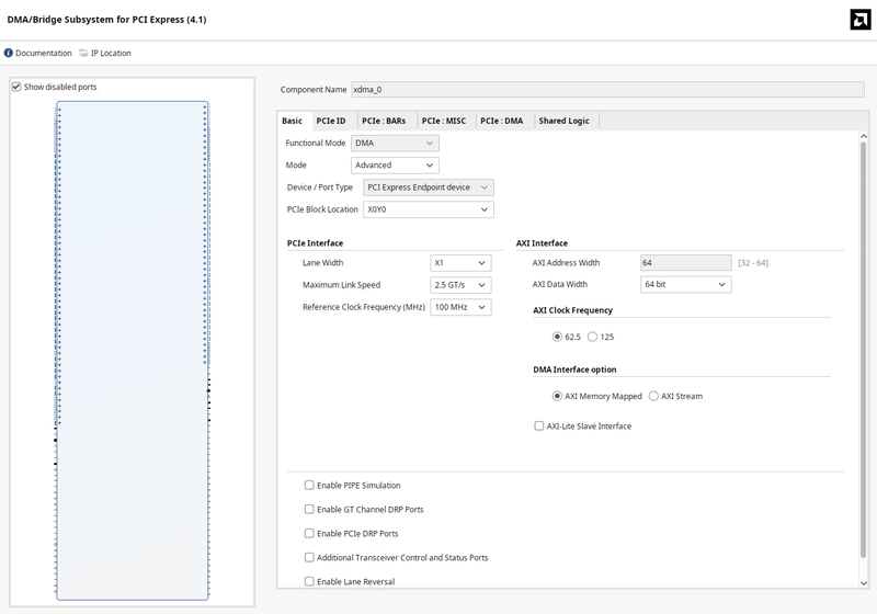
XDMA (PCIe DMA Settings):
AXI PCIe DMA Product Guide (PG195)


-
Channels:
- 1 H2C (Host-to-Card)
- 1 C2H (Card-to-Host)
Request IDs: 32 (read), 16 (write)
AXI ID Width: 4
Descriptor Bypass: Disabled
-
BAR (Base Address Register):
- 1MB AXI Lite space mapped at
0x00000000
- 1MB AXI Lite space mapped at
-
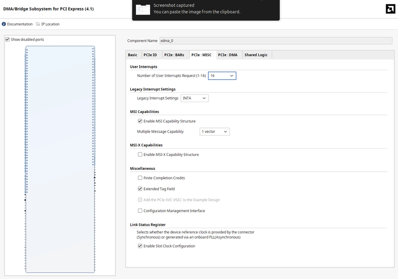
Interrupts:
- MSI enabled
- 16 interrupt vectors
-
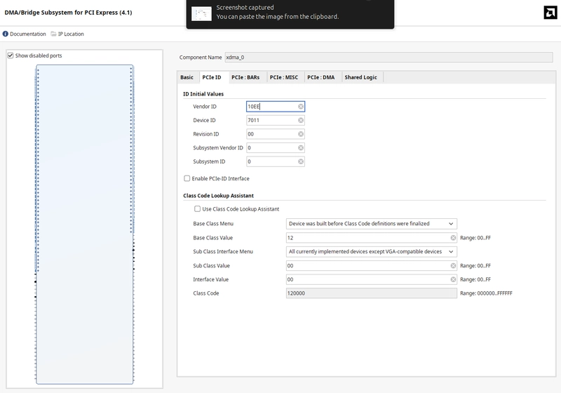
Device Identifiers (PCIe ID)
-
Vendor ID:
10EE(Xilinx) -
Device ID:
7011 -
Class Code:
120000
-
Vendor ID:
PCIe Configuration:
PCIe Base Specification (official summary)
PCIe Gen1 x1 (2.5 GT/s)
AXI Address Width: 64 bits
AXI Data Width: 64 bits
AXI Clock: 125 MHz
Режим: AXI Memory Mapped
UartLite Memory Mapping (Example Setup):
![]()
3. Driver Implementation
3.1 Setting Up the Environment
Hardware Platform:
SDR Board: Custom-built, FPGA Artix-7 200T
GPS Module: SIM68
Interfaces: PCIe, UART
Motherboard: LattePanda Sigma
Software Stack:
OS: Linux Kernel 6.x+
Tools: Vivado, Python, GCC
Debugging:
dmesg,minicom
3.2 Installing Dependencies
sudo apt-get update
sudo apt-get install -y build-essential dkms linux-headers-$(uname -r) git
sudo apt-get install -y pciutils lshw
sudo apt install -y gcc-13 g++-13
sudo apt install -y gpsd gpsd-clients
Packages explanation:
build-essential— GCC, Make, binutils (compiler toolchain)dkms— Dynamic Kernel Module Supportlinux-headers-$(uname -r)— Current kernel headersgit— Git version control systempciutils(lspci) — Inspect PCIe deviceslshw— Hardware information utilitygpsd,gpsd-clients— GPS Daemon and utilities
Check GCC version:
gcc-13 --version
3.3 Hardware Check
Verify that the FPGA board is detected over PCIe:
lspci -d 10ee:
Expected output:
59:00.0 Memory controller: Xilinx Corporation Device 7011
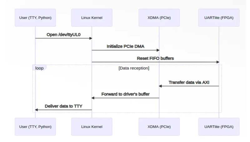
3.4 Driver Implementation
Driver Working Principle
When the module is loaded, the driver registers the PCIe device with Vendor ID 0x10EE and Device ID 0x7011.
It then creates a TTY device /dev/ttyUL0.
Incoming UARTLite data is processed via a workqueue and forwarded into the Linux TTY buffer (tty_flip_buffer_push), making it available for user-space applications.