


![[The AI Show Episode 142]: ChatGPT’s New Image Generator, Studio Ghibli Craze and Backlash, Gemini 2.5, OpenAI Academy, 4o Updates, Vibe Marketing & xAI Acquires X](https://www.marketingaiinstitute.com/hubfs/ep%20142%20cover.png)


![From drop-out to software architect with Jason Lengstorf [Podcast #167]](https://cdn.hashnode.com/res/hashnode/image/upload/v1743796461357/f3d19cd7-e6f5-4d7c-8bfc-eb974bc8da68.png?#)


.png?#)


_Christophe_Coat_Alamy.jpg?#)
 (1).webp?#)


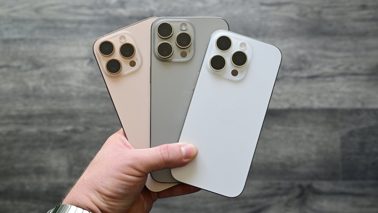


![iPhone 17 Pro Won't Feature Two-Toned Back [Gurman]](https://www.iclarified.com/images/news/96944/96944/96944-640.jpg)
![Tariffs Threaten Apple's $999 iPhone Price Point in the U.S. [Gurman]](https://www.iclarified.com/images/news/96943/96943/96943-640.jpg)


Using STM32 to make a tracking car
Creating a tracking car using an STM32 microcontroller involves integrating sensors, motors, and control algorithms to enable the car to follow a line or avoid obstacles. Below is a step-by-step guide to building a tracking car with STM32: 1. Define the Project Requirements Type of Tracking: Line-following: Use IR sensors to detect a line on the ground. Obstacle avoidance: Use ultrasonic or IR sensors to detect and avoid obstacles. Motor Control: Use DC motors with an H-bridge or motor driver. Power Supply: Ensure the STM32, sensors, and motors are properly powered (e.g., using batteries). Communication: Optional, for remote control or data logging (e.g., UART, Bluetooth, Wi-Fi). 2. Gather Components STM32 Microcontroller: e.g., STM32F4 or STM32F1 series. Motor Driver: e.g., L298N, TB6612FNG, or DRV8833. DC Motors: Two or four motors for movement. Wheels: Matching wheels for the motors. Sensors: Line-following: IR sensors (e.g., TCRT5000). Obstacle avoidance: Ultrasonic sensors (e.g., HC-SR04) or IR distance sensors. Chassis: A frame to hold all components. Power Supply: Batteries (e.g., 9V or LiPo) and voltage regulators (e.g., 5V or 3.3V for STM32). Optional: Bluetooth module (e.g., HC-05) for remote control. 3. Design the Hardware a. Motor Control Connect the motors to the motor driver. Connect the motor driver to the STM32 GPIO pins for PWM control. Example connections for L298N: IN1, IN2, IN3, IN4 → STM32 GPIO pins. ENA, ENB → STM32 PWM pins for speed control. b. Sensor Integration Line-following: Place IR sensors at the front of the car. Connect the sensor outputs to STM32 GPIO pins. Obstacle avoidance: Place ultrasonic sensors at the front and sides. Connect the trigger and echo pins to STM32 GPIO pins. c. Power Supply Use a voltage regulator to provide 3.3V or 5V to the STM32 and sensors. Connect the motor driver directly to the battery. 4. Write the Firmware a. Initialize Peripherals Configure GPIO pins for sensors and motor control. Set up PWM for motor speed control. Initialize ADC (if using analog sensors). Example: c void GPIO_Init(void) { // Configure motor control pins GPIO_InitTypeDef GPIO_InitStruct = {0}; __HAL_RCC_GPIOA_CLK_ENABLE(); GPIO_InitStruct.Pin = GPIO_PIN_0 | GPIO_PIN_1 | GPIO_PIN_2 | GPIO_PIN_3; GPIO_InitStruct.Mode = GPIO_MODE_OUTPUT_PP; GPIO_InitStruct.Pull = GPIO_NOPULL; GPIO_InitStruct.Speed = GPIO_SPEED_FREQ_LOW; HAL_GPIO_Init(GPIOA, &GPIO_InitStruct); } b. Read Sensor Data Line-following: Read the IR sensor outputs to detect the line. Example: c uint8_t Read_IR_Sensors(void) { uint8_t left = HAL_GPIO_ReadPin(GPIOB, GPIO_PIN_0); uint8_t right = HAL_GPIO_ReadPin(GPIOB, GPIO_PIN_1); return (left CNT; while (HAL_GPIO_ReadPin(GPIOB, GPIO_PIN_3)); uint32_t end = TIM2->CNT; return (end - start) * 0.034 / 2; // Distance in cm } c. Implement Control Logic Line-following: Use a PID controller or simple logic to adjust motor speeds based on sensor inputs. Example: c void Line_Following(void) { uint8_t sensors = Read_IR_Sensors(); if (sensors == 0b01) { // Turn left HAL_GPIO_WritePin(GPIOA, GPIO_PIN_0, GPIO_PIN_SET); HAL_GPIO_WritePin(GPIOA, GPIO_PIN_1, GPIO_PIN_RESET); } else if (sensors == 0b10) { // Turn right HAL_GPIO_WritePin(GPIOA, GPIO_PIN_2, GPIO_PIN_SET); HAL_GPIO_WritePin(GPIOA, GPIO_PIN_3, GPIO_PIN_RESET); } else { // Move forward HAL_GPIO_WritePin(GPIOA, GPIO_PIN_0, GPIO_PIN_SET); HAL_GPIO_WritePin(GPIOA, GPIO_PIN_1, GPIO_PIN_SET); } } Obstacle avoidance: Adjust the car's direction based on distance measurements. Example: c void Avoid_Obstacle(void) { float distance = Read_Ultrasonic_Sensor(); if (distance < 20) { // Turn left if obstacle is close HAL_GPIO_WritePin(GPIOA, GPIO_PIN_0, GPIO_PIN_SET); HAL_GPIO_WritePin(GPIOA, GPIO_PIN_1, GPIO_PIN_RESET); } else { // Move forward HAL_GPIO_WritePin(GPIOA, GPIO_PIN_0, GPIO_PIN_SET); HAL_GPIO_WritePin(GPIOA, GPIO_PIN_1, GPIO_PIN_SET); } } d. Main Loop Continuously read sensor data and adjust motor control. Example: c int main(void) { HAL_Init(); SystemClock_Config(); GPIO_Init(); while (1) { Line_Following(); // or Avoid_Obstacle(); } } 5. Test and Debug Test the car on a line or in an obstacle-filled environment. Adjust the control logic and sensor thresholds for optimal performance. Use a debugger (e.g., STM32CubeIDE) to monitor variables and troubleshoot issues. 6. Optional Enhancements Wireless Control: Add a Bluetooth module for remote control. Data Logging: Use UART or an SD card to log sensor data. Advanced Algorithms: Implement advanced control algorithms like PID for smoother tracking. Example Code for Line-Following Car c #include "stm32f4xx.h" void GPIO_Init(void) { // Configure motor control pins G

Creating a tracking car using an STM32 microcontroller involves integrating sensors, motors, and control algorithms to enable the car to follow a line or avoid obstacles. Below is a step-by-step guide to building a tracking car with STM32:
1. Define the Project Requirements
Type of Tracking:
Line-following: Use IR sensors to detect a line on the ground.
Obstacle avoidance: Use ultrasonic or IR sensors to detect and avoid obstacles.
Motor Control: Use DC motors with an H-bridge or motor driver.
Power Supply: Ensure the STM32, sensors, and motors are properly powered (e.g., using batteries).
Communication: Optional, for remote control or data logging (e.g., UART, Bluetooth, Wi-Fi).
2. Gather Components
STM32 Microcontroller: e.g., STM32F4 or STM32F1 series.
Motor Driver: e.g., L298N, TB6612FNG, or DRV8833.
DC Motors: Two or four motors for movement.
Wheels: Matching wheels for the motors.
Sensors:
Line-following: IR sensors (e.g., TCRT5000).
Obstacle avoidance: Ultrasonic sensors (e.g., HC-SR04) or IR distance sensors.
Chassis: A frame to hold all components.
Power Supply: Batteries (e.g., 9V or LiPo) and voltage regulators (e.g., 5V or 3.3V for STM32).
Optional: Bluetooth module (e.g., HC-05) for remote control.
3. Design the Hardware
a. Motor Control
- Connect the motors to the motor driver.
- Connect the motor driver to the STM32 GPIO pins for PWM control.
Example connections for L298N:
IN1, IN2, IN3, IN4 → STM32 GPIO pins.
ENA, ENB → STM32 PWM pins for speed control.
b. Sensor Integration
Line-following:
- Place IR sensors at the front of the car.
- Connect the sensor outputs to STM32 GPIO pins.
Obstacle avoidance:
- Place ultrasonic sensors at the front and sides.
- Connect the trigger and echo pins to STM32 GPIO pins.
c. Power Supply
- Use a voltage regulator to provide 3.3V or 5V to the STM32 and sensors.
- Connect the motor driver directly to the battery.
4. Write the Firmware
a. Initialize Peripherals
- Configure GPIO pins for sensors and motor control.
- Set up PWM for motor speed control.
- Initialize ADC (if using analog sensors).
Example:
c

void GPIO_Init(void) {
    // Configure motor control pins
    GPIO_InitTypeDef GPIO_InitStruct = {0};
    __HAL_RCC_GPIOA_CLK_ENABLE();
    GPIO_InitStruct.Pin = GPIO_PIN_0 | GPIO_PIN_1 | GPIO_PIN_2 | GPIO_PIN_3;
    GPIO_InitStruct.Mode = GPIO_MODE_OUTPUT_PP;
    GPIO_InitStruct.Pull = GPIO_NOPULL;
    GPIO_InitStruct.Speed = GPIO_SPEED_FREQ_LOW;
    HAL_GPIO_Init(GPIOA, &GPIO_InitStruct);
}
b. Read Sensor Data
Line-following:
Read the IR sensor outputs to detect the line.
Example:
c

uint8_t Read_IR_Sensors(void) {
    uint8_t left = HAL_GPIO_ReadPin(GPIOB, GPIO_PIN_0);
    uint8_t right = HAL_GPIO_ReadPin(GPIOB, GPIO_PIN_1);
    return (left << 1) | right;
}
Obstacle avoidance:
Use the ultrasonic sensor to measure distance.
Example:
c

float Read_Ultrasonic_Sensor(void) {
    HAL_GPIO_WritePin(GPIOB, GPIO_PIN_2, GPIO_PIN_SET); // Trigger
    delay_us(10);
    HAL_GPIO_WritePin(GPIOB, GPIO_PIN_2, GPIO_PIN_RESET);
    while (!HAL_GPIO_ReadPin(GPIOB, GPIO_PIN_3)); // Wait for echo
    uint32_t start = TIM2->CNT;
    while (HAL_GPIO_ReadPin(GPIOB, GPIO_PIN_3));
    uint32_t end = TIM2->CNT;
    return (end - start) * 0.034 / 2; // Distance in cm
}
c. Implement Control Logic
Line-following:
Use a PID controller or simple logic to adjust motor speeds based on sensor inputs.
Example:
c

void Line_Following(void) {
    uint8_t sensors = Read_IR_Sensors();
    if (sensors == 0b01) { // Turn left
        HAL_GPIO_WritePin(GPIOA, GPIO_PIN_0, GPIO_PIN_SET);
        HAL_GPIO_WritePin(GPIOA, GPIO_PIN_1, GPIO_PIN_RESET);
    } else if (sensors == 0b10) { // Turn right
        HAL_GPIO_WritePin(GPIOA, GPIO_PIN_2, GPIO_PIN_SET);
        HAL_GPIO_WritePin(GPIOA, GPIO_PIN_3, GPIO_PIN_RESET);
    } else { // Move forward
        HAL_GPIO_WritePin(GPIOA, GPIO_PIN_0, GPIO_PIN_SET);
        HAL_GPIO_WritePin(GPIOA, GPIO_PIN_1, GPIO_PIN_SET);
    }
}
Obstacle avoidance:
Adjust the car's direction based on distance measurements.
Example:
c

void Avoid_Obstacle(void) {
    float distance = Read_Ultrasonic_Sensor();
    if (distance < 20) { // Turn left if obstacle is close
        HAL_GPIO_WritePin(GPIOA, GPIO_PIN_0, GPIO_PIN_SET);
        HAL_GPIO_WritePin(GPIOA, GPIO_PIN_1, GPIO_PIN_RESET);
    } else { // Move forward
        HAL_GPIO_WritePin(GPIOA, GPIO_PIN_0, GPIO_PIN_SET);
        HAL_GPIO_WritePin(GPIOA, GPIO_PIN_1, GPIO_PIN_SET);
    }
}
d. Main Loop
Continuously read sensor data and adjust motor control.
Example:
c

int main(void) {
    HAL_Init();
    SystemClock_Config();
    GPIO_Init();
    while (1) {
        Line_Following(); // or Avoid_Obstacle();
    }
}
5. Test and Debug
- Test the car on a line or in an obstacle-filled environment.
- Adjust the control logic and sensor thresholds for optimal performance.
- Use a debugger (e.g., STM32CubeIDE) to monitor variables and troubleshoot issues.
6. Optional Enhancements
- Wireless Control: Add a Bluetooth module for remote control.
- Data Logging: Use UART or an SD card to log sensor data.
- Advanced Algorithms: Implement advanced control algorithms like PID for smoother tracking.
Example Code for Line-Following Car
c

#include "stm32f4xx.h"

void GPIO_Init(void) {
    // Configure motor control pins
    GPIO_InitTypeDef GPIO_InitStruct = {0};
    __HAL_RCC_GPIOA_CLK_ENABLE();
    GPIO_InitStruct.Pin = GPIO_PIN_0 | GPIO_PIN_1 | GPIO_PIN_2 | GPIO_PIN_3;
    GPIO_InitStruct.Mode = GPIO_MODE_OUTPUT_PP;
    GPIO_InitStruct.Pull = GPIO_NOPULL;
    GPIO_InitStruct.Speed = GPIO_SPEED_FREQ_LOW;
    HAL_GPIO_Init(GPIOA, &GPIO_InitStruct);

    // Configure IR sensor pins
    __HAL_RCC_GPIOB_CLK_ENABLE();
    GPIO_InitStruct.Pin = GPIO_PIN_0 | GPIO_PIN_1;
    GPIO_InitStruct.Mode = GPIO_MODE_INPUT;
    HAL_GPIO_Init(GPIOB, &GPIO_InitStruct);
}

uint8_t Read_IR_Sensors(void) {
    uint8_t left = HAL_GPIO_ReadPin(GPIOB, GPIO_PIN_0);
    uint8_t right = HAL_GPIO_ReadPin(GPIOB, GPIO_PIN_1);
    return (left << 1) | right;
}

void Line_Following(void) {
    uint8_t sensors = Read_IR_Sensors();
    if (sensors == 0b01) { // Turn left
        HAL_GPIO_WritePin(GPIOA, GPIO_PIN_0, GPIO_PIN_SET);
        HAL_GPIO_WritePin(GPIOA, GPIO_PIN_1, GPIO_PIN_RESET);
    } else if (sensors == 0b10) { // Turn right
        HAL_GPIO_WritePin(GPIOA, GPIO_PIN_2, GPIO_PIN_SET);
        HAL_GPIO_WritePin(GPIOA, GPIO_PIN_3, GPIO_PIN_RESET);
    } else { // Move forward
        HAL_GPIO_WritePin(GPIOA, GPIO_PIN_0, GPIO_PIN_SET);
        HAL_GPIO_WritePin(GPIOA, GPIO_PIN_1, GPIO_PIN_SET);
    }
}

int main(void) {
    HAL_Init();
    SystemClock_Config();
    GPIO_Init();
    while (1) {
        Line_Following();
    }
}
By following these steps, you can build a tracking car using an STM32 microcontroller. Customize the design and code based on your specific requirements and components.